Heat dissipation device for flash lamp

A technology of heat dissipation device and flash lamp, which is applied in the direction of lighting device, cooling/heating device of lighting device, optics, etc., can solve the problem of heat transfer to the outside of the mobile terminal, and achieve the effect of avoiding damage

Inactive Publication Date: 2017-01-11
VIVO MOBILE COMM CO LTD
View PDF6 Cites 2 Cited by
  • Summary
  • Abstract
  • Description
  • Claims
  • Application Information

AI Technical Summary

Problems solved by technology

[0004] The invention provides a heat dissipation device for a flash lamp to solve the problem that the ink coating in the prior art cannot effectively transfer the absorbed heat to the outside of the mobile terminal in a timely manner

Method used


Image

  • Heat dissipation device for flash lamp
  • Heat dissipation device for flash lamp

Examples


Embodiment 1

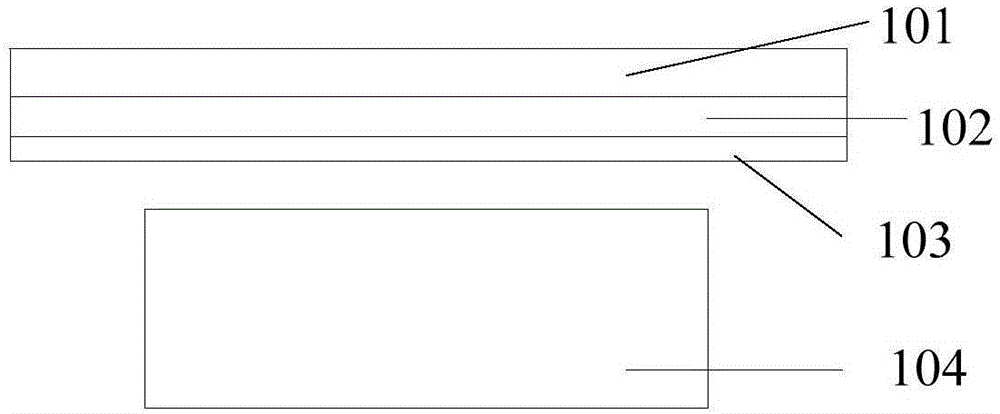
[0012] refer to figure 1 , showing a schematic structural diagram of a flashlight cooling device according to Embodiment 1 of the present invention.

[0013] The flash heat dissipation device of the embodiment of the present invention includes: a glass cover 101 , a heat dissipation layer 102 and an ink coating 103 arranged in sequence;

[0014] It should be noted that those skilled in the art can select the material of the heat dissipation layer according to actual needs, and any material with strong thermal conductivity can be used as the heat dissipation layer, which is not specifically limited.

[0015] In the specific operation process, since the thickness of the mobile terminal is fixed, the thickness of the ink coating and the thickness of the heat dissipation layer will affect the thickness of the mobile terminal, and ultimately affect the appearance of the mobile terminal. Therefore, the thickness of the ink coating and the thickness of the heat dissipation layer Not...

Embodiment 2

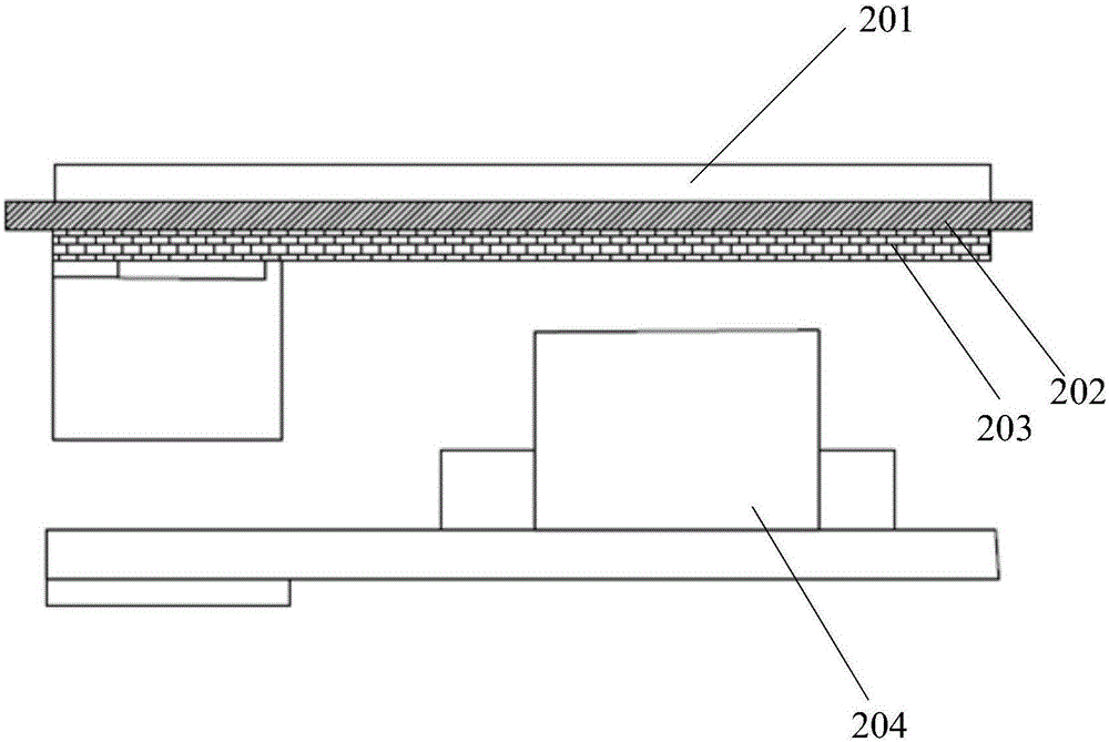
[0020] refer to figure 2 , showing a schematic structural diagram of a flashlight heat dissipation device according to the second embodiment of the present invention.

[0021] The flash heat dissipation device of the embodiment of the present invention includes: a glass cover plate 201 , a heat dissipation layer 202 and an ink coating 203 arranged in sequence;

[0022] The flash can be arranged on the front of the mobile terminal, that is, a front flash.

[0023] In the specific implementation process, the heat dissipation layer is set as a graphene layer, and the thickness is 1 μm˜10 μm.

[0024] Among them, graphene is a nano-material with mechanical properties and thermal conductivity. Its thermal conductivity is as high as 5300 / m·K. Using graphene, a new high-conductivity material, to prepare a heat dissipation layer can effectively improve the ability of thermal diffusion.

[0025] It should be noted that those skilled in the art can select the material of the heat dis...


PUM


Abstract

The invention provides a heat dissipation device for a flash lamp. The heat dissipation device comprises a glass cover plate, a heat dissipation layer and an ink coating layer which are sequentially arranged in an overlapping mode. The ink coating layer is arranged over the flash lamp and is not in contact with the flash lamp. According to the heat dissipation device for the flash lamp, heat generated by the flash lamp in the selfie process can be absorbed by the ink coating layer and can also be conducted out of a mobile terminal through the heat dissipation layer; as the absorbed heat can be effectively transferred out of the mobile terminal in time, local overheating of the mobile terminal will not be caused, and then it can be avoided that the mobile terminal is damaged due to local overheating.

Description

technical field [0001] The present invention relates to the technical field of heat dissipation devices, in particular to a heat dissipation device for flash lamps. Background technique [0002] With the development of mobile terminals, the use of mobile terminals to take selfies has become more and more popular. In order to obtain better shooting effects when taking selfies, supplementary light is often used during shooting. The most convenient way to fill light is to fill light through the front flash of the mobile terminal. [0003] At present, the heat dissipation device of the front flash of the mobile terminal is generally set as follows: an ink coating is arranged on the inner side of the glass cover, and the front flash is arranged just below the ink coating, and the set ink coating is used for the generation of the flash during the use of the flash. However, due to the poor heat dissipation capability of the ink coating, it cannot effectively conduct the heat gener...

Claims


Application Information

Patent Timeline
Patent Type & Authority Applications(China)
IPC IPC(8): G03B15/03F21V29/85F21V29/87
CPCF21V29/85F21V29/87G03B15/03
Inventor 李伟
Owner VIVO MOBILE COMM CO LTD
Why Eureka
Try Eureka