Shared cache distribution method and device
A technology of shared cache and allocation method, applied in the field of service quality, can solve the problem of low cache utilization, and achieve the effect of increasing utilization, improving service quality, and reducing complexity
- Summary
- Abstract
- Description
- Claims
- Application Information
AI Technical Summary
Problems solved by technology
Method used
Image
Examples
Embodiment 1
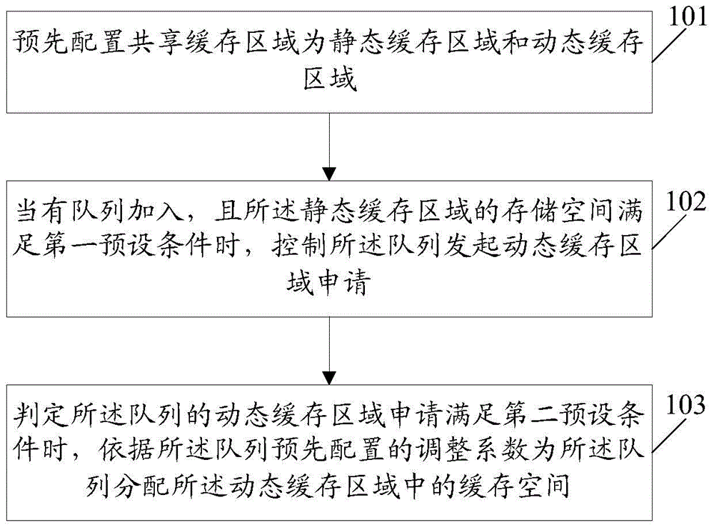
[0040] An embodiment of the present invention provides a shared cache allocation method. figure 1 It is a schematic flow chart of the shared cache allocation method in Embodiment 1 of the present invention; figure 1 As shown, the method includes:
[0041] Step 101: Pre-configure the shared cache space as static cache space and dynamic cache space.
[0042] The shared cache allocation method provided in this embodiment is applied to various network communication devices. Then in this step, the pre-configured shared cache space is a static cache space and a dynamic cache space, which is: the network communication device pre-configures a shared cache space as a static cache space and a dynamic cache space.
[0043] specific, figure 2 It is a schematic diagram of the application of the shared cache space of the embodiment of the present invention; as figure 2 As shown, the network communication device divides the shared cache space into static cache space and dynamic cache s...
Embodiment 2
[0070] The embodiment of the present invention also provides a shared buffer allocation method. Figure 4 It is a schematic flow chart of the method for allocating shared caches in Embodiment 2 of the present invention; Figure 4 As shown, the method includes:
[0071] Step 201: Configure static cache space and dynamic cache space.
[0072] In this embodiment, it is assumed that a group (two) of queues (respectively queue 0 and queue 1, wherein the priority of queue 0 is higher than the priority of queue 1) is used to allocate shared buffer space.
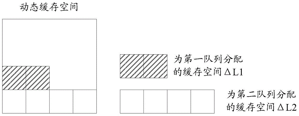
[0073]Here, it is assumed that the total capacity of the shared cache space is 64, the capacity of the static cache space is configured as 32, and the capacity of the dynamic cache space is 32. The priority interval for configuring the dynamic cache space is 16, that is, high priority can occupy up to 32 cache spaces in the dynamic cache space, and low priority can occupy up to 16 cache spaces in the dynamic cache space.
[0074...
Embodiment 3
[0092] The embodiment of the present invention also provides a shared cache allocation device, which can be applied to various network communication devices. Figure 5 It is a schematic diagram of the composition and structure of the shared cache allocation device in Embodiment 3 of the present invention, as shown in Figure 5 As shown, the device includes: a configuration unit 31, a first processing unit 32 and a second processing unit 33; wherein,
[0093] The configuration unit 31 is configured to pre-configure the shared cache space as a static cache space and a dynamic cache space;
[0094] The first processing unit 32 is configured to control the queue to initiate a dynamic cache space application when a queue joins and the storage space of the static cache space satisfies a first preset condition;
[0095] The second processing unit 33 is configured to determine that when the dynamic cache space application for the queue initiated by the first processing unit 32 satisf...
PUM
 Abstract
Description
Claims
Application Information
 - R&D Engineer
- R&D Manager
- IP Professional
- Industry Leading Data Capabilities
- Powerful AI technology
- Patent DNA Extraction
Browse by: Latest US Patents, China's latest patents, Technical Efficacy Thesaurus, Application Domain, Technology Topic, Popular Technical Reports.
© 2024 PatSnap. All rights reserved.Legal|Privacy policy|Modern Slavery Act Transparency Statement|Sitemap|About US| Contact US: help@patsnap.com


