
Device and method for pressing rubber joints to electric motor

A technology of rubber joints and press-fitting devices, applied in metal processing, metal processing equipment, manufacturing tools, etc., to achieve the effect of strong versatility, guaranteeing parallelism requirements, and simple structure

Active Publication Date: 2017-01-18
襄阳中车电机技术有限公司 +1
View PDF8 Cites 3 Cited by
  • Summary
  • Abstract
  • Description
  • Claims
  • Application Information

AI Technical Summary

Problems solved by technology

[0005] In view of this, the object of the present invention is to provide a motor rubber node press-fitting device and method to solve the technical problem of directly pressing the rubber node on the motor

Method used


Image

  • Device and method for pressing rubber joints to electric motor
  • Device and method for pressing rubber joints to electric motor
  • Device and method for pressing rubber joints to electric motor

Examples


Embodiment 1

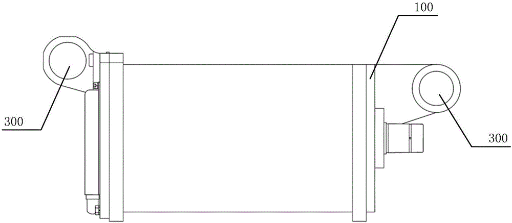
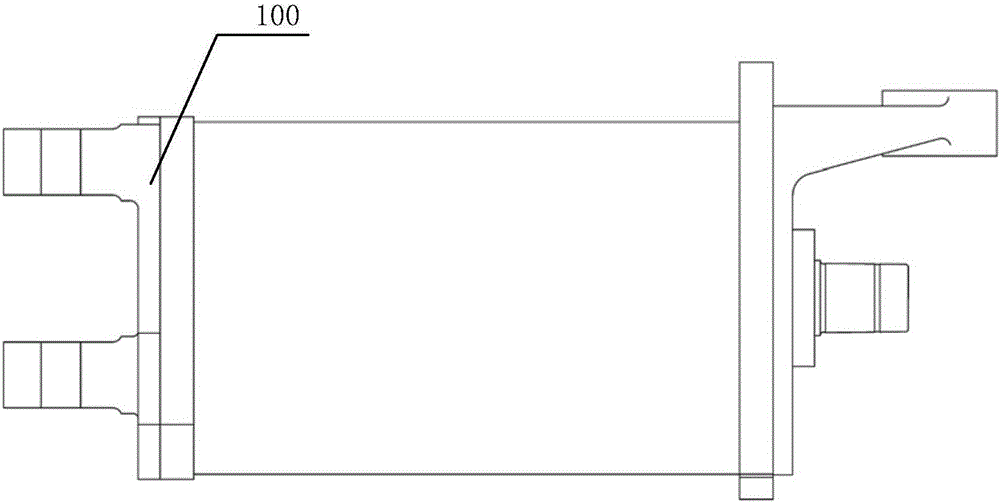
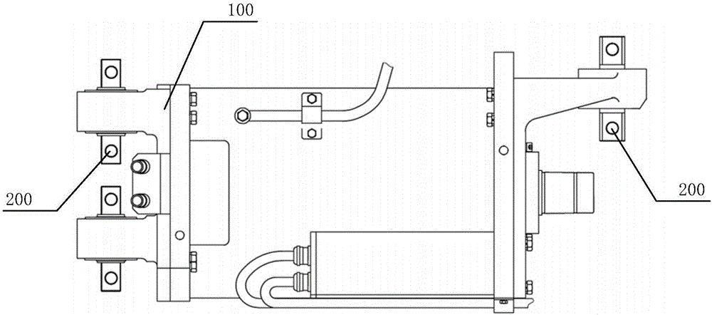
[0053] as attached Figure 7 As shown, a specific embodiment of a motor rubber node press-fitting device is used to press-fit the rubber node 200 into the rubber node installation hole 300 of the motor end cover 100. The press-fitting device includes:

[0054] The bottom plate 1, the guide plate 1, the guide plate 2 5 and the splint 7 are spaced apart and coaxially arranged in sequence according to the assembly positions, and the guide plate 1 4, the guide plate 2 5 and the splint 7 are all provided with through holes, such as attached Figure 9 And attached Figure 10 Shown is the schematic diagram of the structure of the base plate 1, as attached Figure 13 And attached Figure 14 Shown is the structural diagram of the splint 7; there is a space for arranging the force-applying mechanism 10 between the bottom plate 1 and the guide plate 1, and a space for accommodating the rubber node installation hole 300 is arranged between the guide plate 2 5 and the splint 7;

[0055...

Embodiment 2

[0067] A specific embodiment of a method for press-fitting a rubber node of a motor using the device described above includes the following steps:


PUM


Abstract

The invention discloses a device and method for pressing rubber joints to an electric motor. The device comprises a bottom plate, a pressing block, a pressing sleeve, a first guide plate, a second guide plate, a clamping plate and a guide bar, wherein the bottom plate, the first guide plate, the second guide plate and the clamping plate are sequentially arranged in spaced and coaxial modes; the guide bar is arranged in the bottom plate, the first guide plate, the second guide plate and the clamping plate in a penetrating mode; a space for containing rubber joint installation holes is reserved between the second guide plate and the clamping plate; the pressing block is arranged in the position, facing one side of the bottom plate, of the first guide plate; the pressing sleeve is arranged in the through hole of the first guide plate in a penetrating mode and makes contact with the pressing block; and the pressing sleeve is provided with inner holes used for containing the flat portions of one end of the rubber joints. When the joints are to be pressed, a stress application mechanism arranged between the bottom plate and the first guide plate is used for transferring pressing force to the rubber joints sequentially through the pressing block and the pressing sleeve, the pressing block, the pressing sleeve and the first guide plate move towards the side where the second guide plate is located, and accordingly the rubber joints are pressed into the rubber joint installation holes. The device and method can achieve the technical purpose of directly pressing the rubber joints onto the electric motor.

Description

technical field [0001] The invention relates to the field of tooling equipment, in particular to a rubber node press-fitting device and method applied to rail transit motors. Background technique [0002] The rubber nodes of the motor mainly play the role of positioning and vibration reduction in the entire motor installation structure, so the installation of rubber nodes has a great influence on the running quality and stress state of the motor. If the rubber joint is not installed properly, it will not only fail to absorb vibration and shock, but will also cause these vibration and shock to be directly transmitted to the metal structure related to it, which will aggravate the stress condition of the motor and cause abnormal operation of the motor. [0003] as attached Figure 5 and 6 As shown, the rubber node 200 generally includes an outer steel ring 201 , a rubber 202 , an inner steel ring 203 and a flat square 204 arranged coaxially in sequence from outside to inside. ...

Claims


Application Information

Patent Timeline
Patent Type & Authority Applications(China)
IPC IPC(8): B23P19/027
CPCB23P19/027
Inventor 陈佳王新剑黄谷香王鹏黄杰殷茜
Owner 襄阳中车电机技术有限公司
Learn More