Storage box for precise power supply instrument

A technology for storage boxes and instruments, applied in containers, rigid containers, assembly machines, etc., can solve the problems of lack of protection measures, heavy weight, and reduced performance and life of precision power supply instruments

Inactive Publication Date: 2017-01-18
STATE GRID SHANDONG ELECTRIC POWER +1
View PDF6 Cites 8 Cited by
  • Summary
  • Abstract
  • Description
  • Claims
  • Application Information

AI Technical Summary

Problems solved by technology

[0002] At present, precision power supply instruments are generally simply placed in the room without any protection measures, resulting in a reduction in the performance and life of precision power supply instruments
[0003] In the patent document with the publication number CN103935633A, a moisture-proof storage box for precision power supply instruments is disclosed, including a box body, a box cover is provided on the top of the box body, and an instrument pallet is installed on the bottom of the box body, and the instrument pallet holds the box. The internal cavity is divided into a storage chamber and a moisture absorption chamber, and the instrument pallet is provided with a pallet ventilation hole connecting the storage chamber and the moisture absorption chamber, and a drawer hole is provided on the side wall of the box corresponding to the moisture absorption chamber , the drawer hole is plugged with a moisture-absorbing drawer extending into the moisture-absorbing cavity, the moisture-absorbing drawer and the drawer hole are sealed, and a moisture-absorbing agent is placed in the moisture-absorbing drawer; because the precision power supply instrument is relatively precise and heavy, it is easy to store Often multiple storage boxes are stacked together. The invention can replace the hygroscopic agent without moving the storage box and the instrument. The instrument can be placed in the box for any period of time, ensuring the reliability and reliability of the precision power supply instrument. Normal service life; however, the invention does not involve fixation and temperature issues of precision power supply instruments

Method used


Image

  • Storage box for precise power supply instrument

Examples


Embodiment

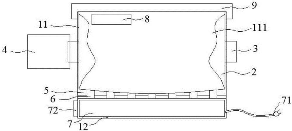
[0016] Such as figure 1 As shown, a storage box for a precision power supply instrument in this embodiment includes a box body 11, and the box body 11 is provided with an accommodating chamber 111 with an upward opening. The lower end of the box body 11 is connected with an installation box 12. An airbag 2 is provided, and an inflation port 3 connected to the airbag 2 is provided on the outside of the box body 11, and the inflation port 3 is connected with the inflation device 4; a buffer layer 5 is provided on the bottom surface of the accommodating cavity 111, and a plurality of through holes are provided on the buffer layer 5 6. The through hole 6 passes through the bottom side of the box body 11 and communicates with the installation box 12; the air conditioner 7 is installed in the installation box 12.

[0017] In this embodiment, a temperature and humidity detector 8 for monitoring the temperature and humidity in the accommodating cavity 111 is provided on the side of th...


PUM


Abstract

The invention provides a storage box for a precise power supply instrument and relates to the technical field of precise power supply instruments. The storage box comprises a box body. A containing cavity with an upward opening is formed in the box body. The lower end of the box body is connected with an installation box. An air bag is arranged on the side wall of the containing cavity. The outer side of the box body is provided with an inflation opening connected with the air bag. The inflation opening is connected with the inflation device in a matched manner. A buffering layer is arranged on the bottom face of the containing cavity. Multiple through holes are formed in the buffering layer. The through holes penetrate the bottom side of the box body and communicate with the installation box. An air conditioner is arranged in the installation box. The storage box is simple in structure, the precise power supply instrument can be effectively fixed, and good temperature and humidity can also be provided for the precise power supply instrument.

Description

technical field [0001] The invention relates to the technical field of precision power supply instruments, in particular to a storage box for precision power supply instruments. Background technique [0002] At present, precision power supply instruments are generally simply placed in the room without any protection measures, resulting in a reduction in the performance and life of precision power supply instruments. [0003] In the patent document with the publication number CN103935633A, a moisture-proof storage box for precision power supply instruments is disclosed, including a box body, a box cover is provided on the top of the box body, and an instrument pallet is installed on the bottom of the box body, and the instrument pallet holds the box. The internal cavity is divided into a storage chamber and a moisture absorption chamber, and the instrument pallet is provided with a pallet ventilation hole connecting the storage chamber and the moisture absorption chamber, and...

Claims


Application Information

Patent Timeline
Patent Type & Authority Applications(China)
IPC IPC(8): B65D81/05B65D81/18B65D25/20B65D81/26B65D85/68
CPCB65D81/05B65D25/20B65D81/052B65D81/18B65D81/266B65D85/68
Inventor 毕安宁吕胜军亓振新边金龙李祥莹徐继凯许少健张海霞吕金亮潘佳刘晓艳许强张斌陈兴连朱晓阳崔东海郝强朱伟波董梅王慧
Owner STATE GRID SHANDONG ELECTRIC POWER
Why Eureka
Try Eureka