Electrolysis device and electrolysis method
A technology of an electrolysis device and an electrolysis method, applied in the field of electrolysis, can solve problems such as the dead zone of the electrolytic cell flow, and achieve the effects of enhancing heat and mass transfer, enhancing fluidity, and slowing down nodules
- Summary
- Abstract
- Description
- Claims
- Application Information
AI Technical Summary
Problems solved by technology
Method used
Image
Examples
Embodiment 1
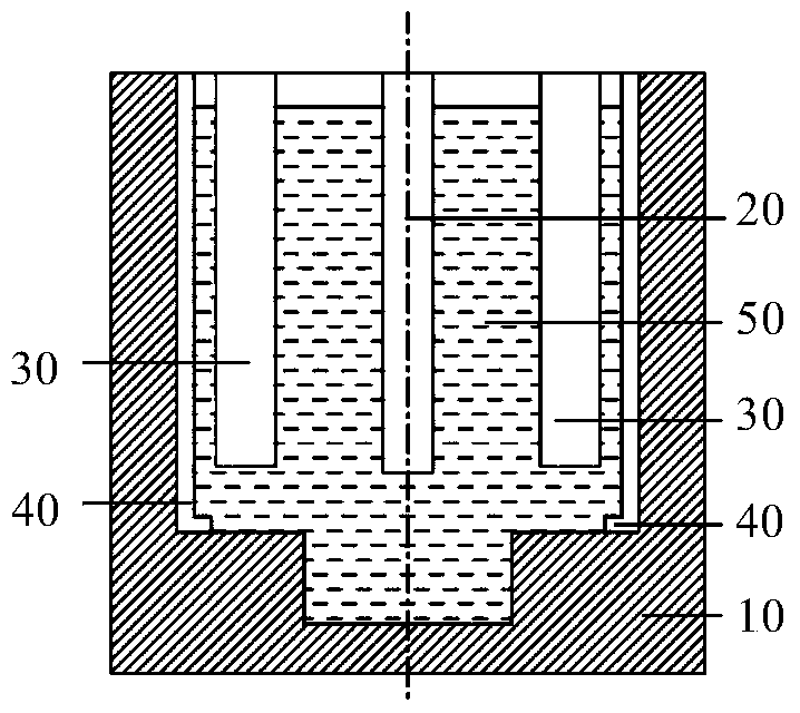
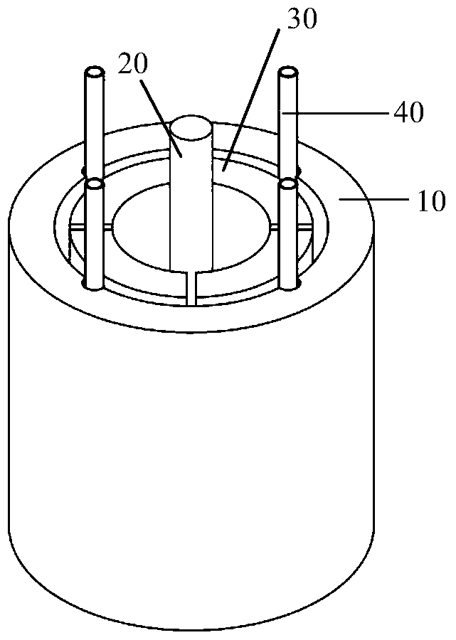
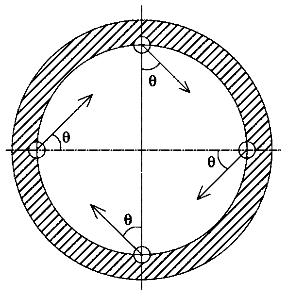
[0068] Take NdF 3 and LiF mixture as a molten salt electrolyte, where NdF 3 The mass ratio to LiF is 7:1, graphite is used as anode, molybdenum rod is used as cathode, electrolysis is performed at 1050°C, the electrolysis voltage is 8.5V, and the flow rate of gas in the ventilation pipe is controlled to 4.0×10 -5 m 3 / s, the angle between the direction of the gas outlet and the normal direction of the inner wall of the electrolytic cell is 30°, under the action of direct current, the added Nd 2 o 3 Nd in 3+ precipitated on the surface of the cathode. The metal droplets are formed and fall into the molybdenum crucible at the bottom of the electrolytic cell. After 2 hours of electrolysis, the metal droplets are scooped out and poured into the mold. No nodules were found at the bottom of the side wall of the furnace after working for 72 hours.
[0069] Main technical indicators: current efficiency is 88.0%, carbon content is 200ppm, iron content is 500ppm, and the service l...
Embodiment 2
[0071] Take NdF 3 and LiF mixture as a molten salt electrolyte, where NdF 3 The mass ratio to LiF is 7:1, graphite is used as anode, molybdenum rod is used as cathode, electrolysis is performed at 1050°C, electrolysis voltage is 8.5V, and the flow rate of gas in the ventilation pipe is controlled to 7.0×10 -5 m 3 / s, under the action of direct current, the added Nd 2 o 3 Nd in 3+ precipitated on the surface of the cathode. The metal droplets are formed and fall into the molybdenum crucible at the bottom of the electrolytic cell. After 2 hours of electrolysis, the metal droplets are scooped out and poured into the mold. The bottom of the side wall of the furnace body has not been found to have nodulation phenomenon after working for 100 hours.
[0072] Main technical indicators: current efficiency is 90.0%, carbon content is 190ppm, iron content is 450ppm, and the service life of a single anode is 96-104h.
Embodiment 3
[0074] to DyF 3 and LiF mixture as a molten salt electrolyte, where DyF 3 The mass ratio to LiF is 6:1, with graphite as the anode and iron rod as the cathode, electrolyze at 1080°C, the electrolysis voltage is 10.0V, and the flow rate of the gas in the ventilation pipe is controlled to 5.0×10 -5 m 3 / s, the angle between the direction of the gas outlet and the normal direction of the inner wall of the electrolytic cell is 45°, under the action of direct current, the added Dy 2 o 3 Dy in 3+ It precipitates on the surface of the cathode and interacts with the iron cathode to form DyFe alloy droplets, which fall into the iron crucible at the bottom of the electrolytic cell. After 2 hours of electrolysis, the iron crucible is lifted out, and the alloy droplets obtained by electrolysis are poured into the mold. There was no nodulation at the bottom of the side wall of the furnace after working for 80 hours.
[0075] Main technical indicators: current efficiency 87%, carbon co...
PUM
| Property | Measurement | Unit |
|---|---|---|
| current efficiency | aaaaa | aaaaa |
| current efficiency | aaaaa | aaaaa |
| current efficiency | aaaaa | aaaaa |
Abstract
Description
Claims
Application Information
 - R&D
- Intellectual Property
- Life Sciences
- Materials
- Tech Scout
- Unparalleled Data Quality
- Higher Quality Content
- 60% Fewer Hallucinations
Browse by: Latest US Patents, China's latest patents, Technical Efficacy Thesaurus, Application Domain, Technology Topic, Popular Technical Reports.
© 2025 PatSnap. All rights reserved.Legal|Privacy policy|Modern Slavery Act Transparency Statement|Sitemap|About US| Contact US: help@patsnap.com


