

A large field of view mid-wave infrared optical athermalization system
A technology of infrared optics and large field of view, applied in the field of optics, can solve the problem that the influence of infrared optical system is particularly serious, and achieve the effect of reducing distortion and eliminating thermal difference
Inactive Publication Date: 2012-07-25
LUOYANG INST OF ELECTRO OPTICAL EQUIP OF AVIC
View PDF0 Cites 4 Cited by
- Summary
- Abstract
- Description
- Claims
- Application Information
AI Technical Summary
Problems solved by technology
The temperature range of the working environment of most airborne military optical instruments is relatively large. When the temperature changes, the curvature, thickness, and refractive index of the optical elements will change. Because the temperature coefficient of refractive index of infrared optical materials is one or two larger than that of visible light materials Therefore, the impact of environmental temperature changes on the infrared optical system is particularly serious, so an active or passive compensation mechanism must be added to the infrared imaging system to compensate for the system performance degradation caused by the movement of the image plane caused by temperature changes
Method used
View moreImage
Smart ImageViewing Examples

Examples
Embodiment Construction
Login to View More PUM
 Abstract
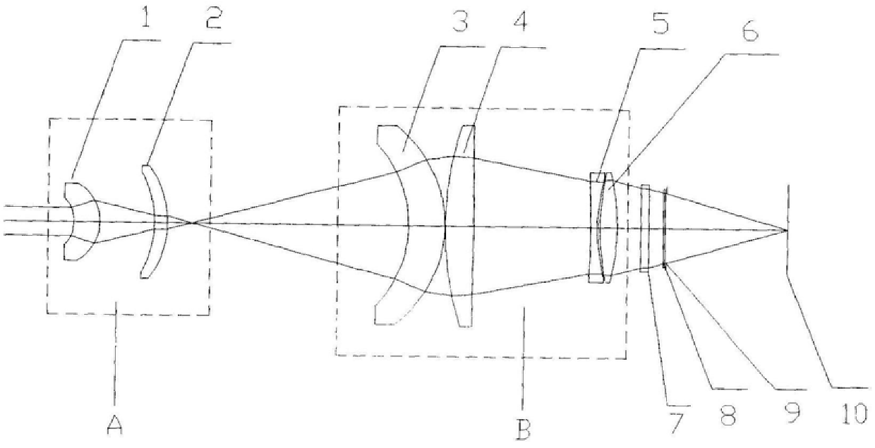
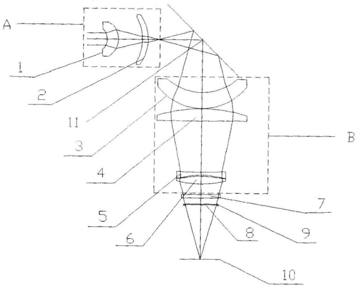
The present invention is a medium-wave infrared optical athermalization system with a large field of view, which includes a primary imaging objective lens A, a secondary imaging objective lens B, a detector protection light window, a detector filter and a cold diaphragm, and is characterized in that: a primary imaging Objective lens A is composed of lens I and lens II, and adopts a convex-convex lens configuration. The focal length of primary imaging objective lens A is 11.65mm, and both lens I and lens II are convex lenses; secondary imaging objective lens B is composed of lens III, lens IV, lens V, Lens VI is composed of a convex-convex lens layout. The focal length of the secondary imaging objective lens B is 30.07mm. Both lens III and lens IV are convex lenses. The focal length of lens III and lens IV is 29.67mm. Lens V(5) is Concave lens, lens VI (6) is a convex lens; the focal length of lens V and lens VI is 73.74mm; the distance between primary imaging objective lens A and secondary imaging objective lens B is 51.02mm. The effect of the technical solution of the present invention is: 1. In a wide temperature range (-40 ℃~+60 ℃), the imaging quality of the optical system is higher, the center field of view, the MTF value at 20lp / mm is not less than 0.55, and the edge field of view, The MTF value at 20lp / mm is not less than 0.55; 2. The distortion of the large field of view is small, and the distortion of the full field of view is less than 5%.
Description
A large field of view mid-wave infrared optical athermalization system technical field The invention is a medium-wave infrared optical athermalization system with a large field of view, which belongs to the field of optical technology. Background technique The temperature range of the working environment of most airborne military optical instruments is relatively large. When the temperature changes, the curvature, thickness, and refractive index of the optical elements will change. Because the temperature coefficient of refractive index of infrared optical materials is one or two larger than that of visible light materials Therefore, the impact of environmental temperature changes on the infrared optical system is particularly serious, so an active or passive compensation mechanism must be added to the infrared imaging system to compensate for the system performance degradation caused by the image plane movement caused by temperature changes. Contents of the invention T...
Claims
Login to View More Application Information
Patent Timeline
 IPC IPC(8): G02B27/00G02B13/14
Inventor王希军
OwnerLUOYANG INST OF ELECTRO OPTICAL EQUIP OF AVIC