Steel plate drilling device

A drilling device, steel plate technology, applied in the direction of positioning device, boring/drilling, drilling/drilling equipment, etc., can solve the problems of expensive purchase, easy falling off of metal plates, increase of defective products, etc., and reach the drilling position Accurate, reduce temperature, reduce the effect of defective products

Active Publication Date: 2017-01-25
日照德信机械制造有限公司
View PDF6 Cites 32 Cited by
  • Summary
  • Abstract
  • Description
  • Claims
  • Application Information

AI Technical Summary

Problems solved by technology

[0002] At present, metal steel plates are widely used in mechanical structural components such as petroleum, chemical industry, medical treatment, food, light industry, mechanical instruments, etc., and have become an indispensable material. Usually, it is common to drill metal plates. Processing method, drilling refers to the operation of using a drill to process holes in solid materials, but the current drilling equipment is either too precise and expensive to purchase, which increases the processing cost, and the gain outweighs the gain; or it is too simple and the processing is too rough to achieve To the production standard; and some drilling equipment vibrates too much when drilling after the metal plate is placed, and the metal plate is easy to shake from side to side, which changes the size of the drilling hole and increases the generation of defective products, and high-strength drilling The metal plate is easy to fall off during the process, interrupting the processing and affecting work efficiency

Method used


Image

  • Steel plate drilling device
  • Steel plate drilling device

Examples


Embodiment Construction

[0014] The following will clearly and completely describe the technical solutions in the embodiments of the present invention with reference to the accompanying drawings in the embodiments of the present invention. Obviously, the described embodiments are only some of the embodiments of the present invention, not all of them. Based on the embodiments of the present invention, all other embodiments obtained by persons of ordinary skill in the art without making creative efforts belong to the protection scope of the present invention.

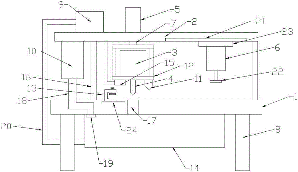
[0015] Please refer to the figure, in the embodiment of the present invention, a steel plate drilling device includes a frame 1, a motor 3, a drill bit 4 and legs 8; the legs 8 are fixed around the frame 1; The left and right ends of the frame 1 are fixedly provided with a vertical column 16, and the upper end of the column 16 is fixedly connected with a horizontal top plate 2, and a first hydraulic cylinder 5 is fixedly installed on the top plate...


PUM


Abstract

The invention discloses a steel plate drilling device. The steel plate drilling device comprises a frame, a motor, a drilling head and support legs, wherein the motor is mounted on a motor frame; the drilling head is fixedly mounted on an output shaft of the motor; a laser lamp is mounted on the lower side of the motor frame via a universal joint; one end of an air extractor is communicated with an air extracting pipe; the air extracting pipe is communicated with the inside of a water tank; a sliding groove is formed in the upper surface of the frame, and is slidably connected with a fixing device; the fixing device comprises a vertical plate, an upper transverse plate, a lower transverse plate, a movable plate, a bolt and a magnet block; a horizontal sliding rail is fixed on the lower side of the right end of a top plate, and is slidably connected with a sliding block; a second hydraulic cylinder is fixedly arranged on the sliding block; a horizontal pressing plate is fixedly mounted at the lower end of the second hydraulic cylinder. According to the steel plate drilling device, the fixing device is used for fixing up-and-down vibration of a steel plate; the pressing plate is capable of limiting left-and-right sliding motion of the steel plate; the steel plate can be firmly fixed; great errors caused by vibration of equipment can be avoided; the occurrence of defective products can be reduced; the laser lamp is used for positioning the steel plate and enabling a drilling position to be more accurate.

Description

technical field [0001] The invention relates to a steel plate processing equipment, in particular to a steel plate drilling device. Background technique [0002] At present, metal steel plates are widely used in mechanical structural components such as petroleum, chemical industry, medical treatment, food, light industry, mechanical instruments, etc., and have become an indispensable material. Usually, it is common to drill metal plates. Processing method, drilling refers to the operation of using a drill to process holes in solid materials, but the current drilling equipment is either too precise and expensive to purchase, which increases the processing cost, and the gain outweighs the gain; or it is too simple and the processing is too rough to achieve To the production standard; and some drilling equipment vibrates too much when drilling after the metal plate is placed, and the metal plate is easy to shake from side to side, which changes the size of the drilling hole and...

Claims


Application Information

Patent Timeline
Patent Type & Authority Applications(China)
IPC IPC(8): B23B41/00B23B47/00B23Q3/08B23Q3/06B23Q11/00B23Q11/10
CPCB23B41/00B23B47/00B23Q3/062B23Q3/082B23Q11/0046B23Q11/10
Inventor 不公告发明人
Owner 日照德信机械制造有限公司
Why Eureka
Try Eureka