
cam key

A positioning key and cam technology, which is applied to metal processing machinery parts, metal processing equipment, feeding devices, etc., can solve the problems affecting the positioning accuracy and repeat positioning accuracy, the force of the pin shaft and the rigidity of the transmission, and the accuracy of the attachment milling head. To meet the requirements and other issues, to achieve the effect of compact structure, good positioning accuracy and repeat positioning accuracy, cutting rigidity and simple structure

Active Publication Date: 2018-06-29
CHANGZHOU INST OF MECHATRONIC TECH
View PDF6 Cites 0 Cited by
  • Summary
  • Abstract
  • Description
  • Claims
  • Application Information

AI Technical Summary

Problems solved by technology

[0003] In the existing technology, the existing accessory milling head uses a pin shaft for positioning after rotation. The problem of the force of the pin shaft and the rigidity of the transmission has always been a major issue in front of every machine tool manufacturer.
Most of the pin holes are processed by coordinate boring, and the position accuracy of the holes is high, but the fit gap between the hole shafts is difficult to eliminate, and the force on the pin shaft is a line, and the bearing capacity is also small, which will directly affect the positioning accuracy of the accessory milling head after rotation and repeated positioning accuracy, so that the accuracy of the accessory milling head cannot meet the requirements

Method used


Image

  • cam key
  • cam key
  • cam key

Examples


Embodiment Construction

[0021] In order to make the content of the present invention more clearly understood, the present invention will be further described in detail below based on specific embodiments and in conjunction with the accompanying drawings.

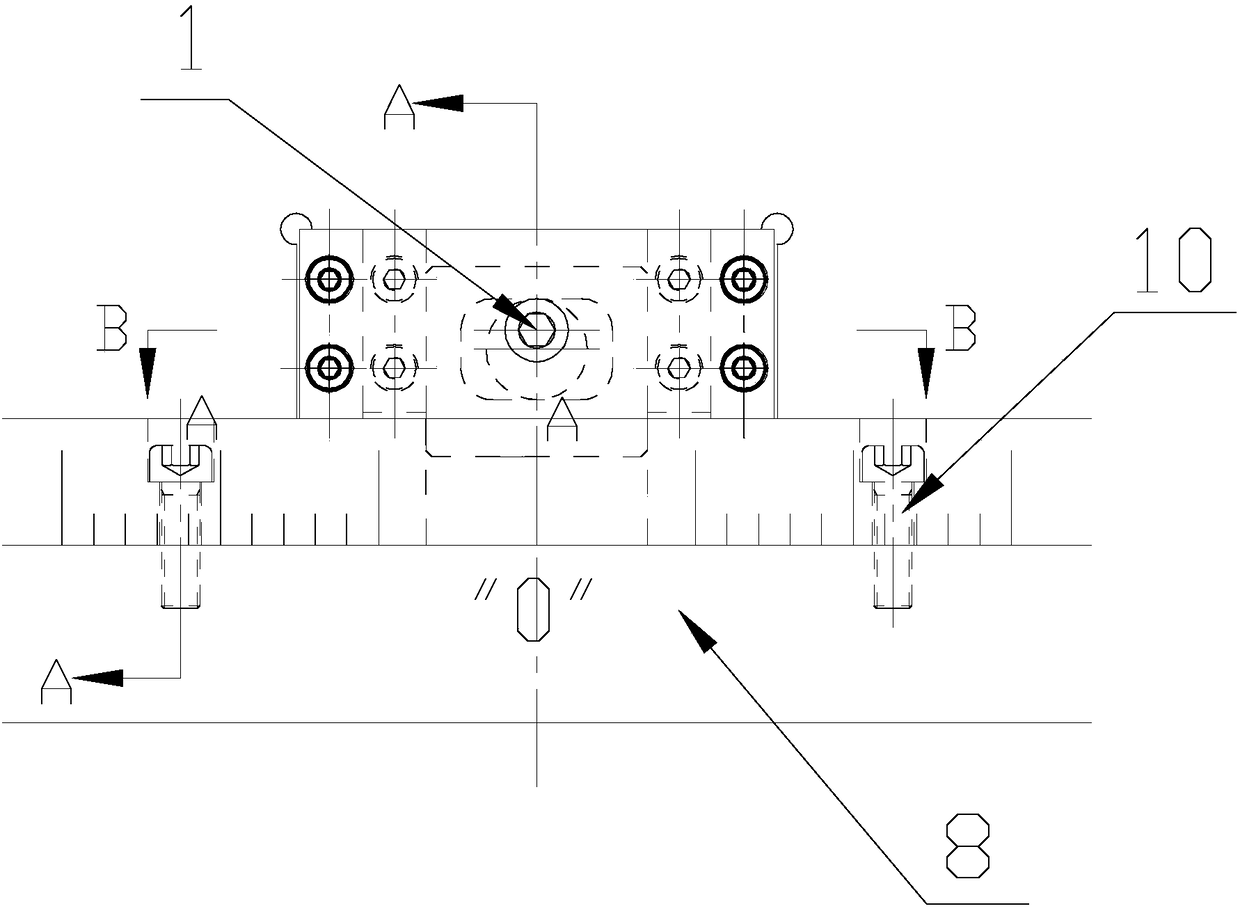
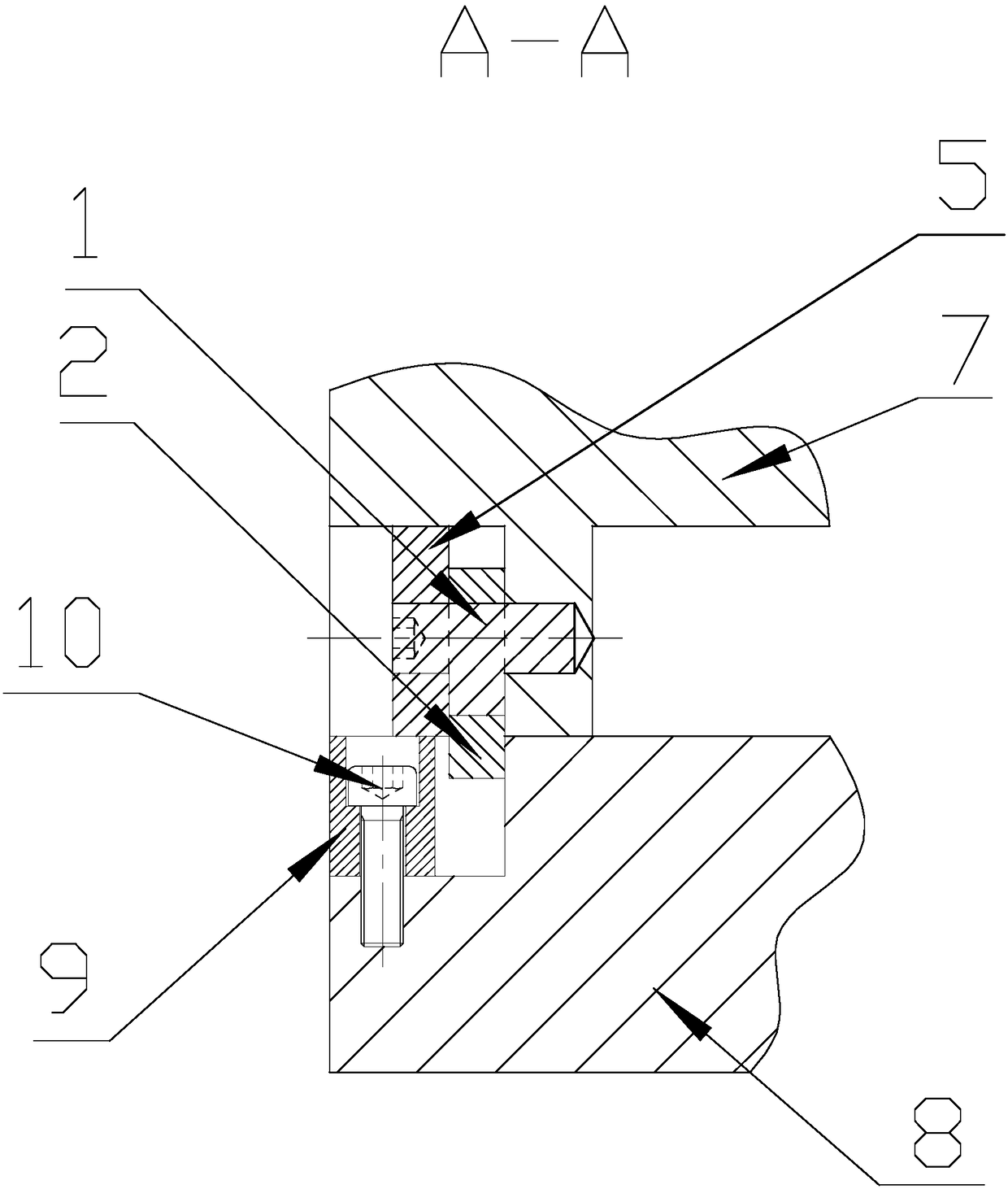
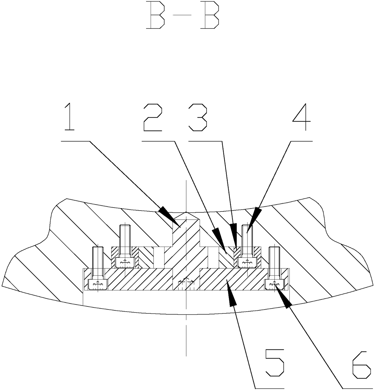
[0022] Such as figure 1 , figure 2 , image 3 , Figure 4 , Figure 5 , Figure 6 As shown, a cam positioning key includes an upper rotary body 7, a cam, a stopper 3, a pressure plate 5, a hollow positioning key 2 and a lower rotary body 8, and the stopper 3 is fixedly connected to the upper rotary body 7 by screws 4 Above, the pressing plate 5 is fixedly connected to the upper rotating body 7 through screws 6, the cam has an eccentrically arranged camshaft 1, one end of the camshaft 1 is fixedly connected to the upper rotating body 7, and the other end is fixedly connected to the pressing plate 5, the The hollow positioning key 2 is set outside the cam, and the stopper 3, the pressure plate 5 and the upper rotary body 7 together form a slidi...


PUM


Abstract

The invention discloses a novel cam positioning key. The novel cam positioning key comprises an upper rotation solid, a cam, stopping blocks, a pressing plate, a hollow positioning key and a lower rotation solid. The stopping blocks and the pressing plate are fixedly connected on the upper rotation solid, the cam has a cam shaft eccentrically arranged, one end of the cam shaft is fixedly connected on the upper rotation solid, the other end of the cam shaft is fixedly connected on the pressing plate, the cam is sleeved with the hollow positioning key, and sliding space allowing the positioning key to slide in the space up and down is defined by the stopping blocks, the pressing plate and the upper rotation solid; a positioning groove matched with the positioning key is formed in the upper end of the lower rotation solid, and after the lower rotation solid rotates in place, the hollow positioning key slides downwards along with the rotating of the cam shaft and is inserted into the position groove. According to the novel cam positioning key, the hollow positioning key is driven through rotating of the cam to slide up and down, can be inserted into the positioning groove in the lower rotation solid when sliding downwards, the upper rotation solid and the lower rotating solid are located in the positioning state and cannot rotate each other, positioning is carried out through the positioning key, the contact mode is the surface contact mode, the positioning area is large, and the transmission rigidity is high.

Description

technical field [0001] The invention relates to a cam positioning key, in particular to a device suitable for positioning the milling head of an accessory of a large-scale gantry boring and milling machining center and a floor boring and milling machining center after rotation, and belongs to the technical field of mechanical structures. Background technique [0002] With the rapid development of my country's machinery industry, especially the development of heavy industry, there is an increasing demand for large-scale metal processing equipment such as CNC gantry boring and milling machining centers and CNC floor boring and milling machining centers; Positioning also puts forward higher requirements. [0003] In the prior art, a pin shaft is used for positioning after the existing accessory milling head rotates, and the force bearing and transmission rigidity of the pin shaft have always been a major problem facing various machine tool manufacturers. Most of the pin holes a...

Claims


Application Information

Patent Timeline
Patent Type & Authority Patents(China)
IPC IPC(8): B23Q5/34
CPCB23Q5/345B23Q2705/104
Inventor 叶穗黄俊桂
Owner CHANGZHOU INST OF MECHATRONIC TECH
Learn More