Mechanical sealing device with axial adjusting function for large-sized dredger sludge pump

A mechanical seal device and axial adjustment technology, which is applied to parts of pumping devices for elastic fluids, mechanical equipment, pumps for special fluids, etc., can solve the problem of reducing the utilization rate of mud pump equipment, aggravating the wear of sealing rings, and sealing Unstable use effect and other problems, to achieve the effect of ensuring reliability and maintenance convenience, ensuring concentricity and followability, convenient transportation and on-site installation

Active Publication Date: 2017-01-25
天津市合润科技有限责任公司
View PDF9 Cites 5 Cited by
  • Summary
  • Abstract
  • Description
  • Claims
  • Application Information

AI Technical Summary

Problems solved by technology

This kind of sealing device is suitable for a narrow range of working conditions, and its service life is unstable. The actual service life is mostly 1 to 6 months. It is affected by deflection, vibration, sharp particles and solid particle abrasion, marine organisms, and pump pressure conditions. As a result, the sealing effect is unstable, frequent eccentric wear and severe abrasive wear lead to a shortened service life of the system (the actual service life is mostly 1 to 6 months)
The maintenance and disassembly of large dredge pumps takes a lot of time and the cycle is long, which reduces the equipment utilization rate of dredge pumps, not only consumes a lot of maintenance funds, but also wastes a lot of precious construction time of dredgers
[0003] In the existing mechanical seal structure, the spring is a fixed and non-adjustable element after installation. However, due to the constraints of the pump body structure and installation dimensions on the special pump, the stability of the working height of the spring cannot be guaranteed. This instability directly Affects the spring specific pressure of the mechanical seal
The spring force mainly acts between the dynamic and static rings of the seal to prevent the sealing end face from opening when the equipment is started, stopped or the medium pressure fluctuates, so that the compensation ring can follow the end face and apply a closing force in the axial direction. The spring specific pressure is too small to play the above role, and vice versa Too large aggravates the wear of the seal ring, affecting the reliability and service life of the entire mechanical seal
[0004] Especially for split mechanical seals, the adjustment gap between the pump chamber and the impeller is large. When the mechanical seal is installed, the working height of the spring changes due to the adjustment of the impeller clearance of the pump, so that the specific pressure of the spring cannot obtain a stable design data, so it becomes a mechanical seal. A difficult point in the design of sealing structure
[0005] In addition, the applicant submitted a request for a search report on this application to the Patent Search and Consultation Center of the State Intellectual Property Office before submitting the application, the case number is G1611175, and the patent types cited in the search report are all "A" files, that is, background technology documents , that is, reflecting part of the technical features of the claims or part of the relevant prior art documents; CN201858359U, CN201215106Y, CN2542859, WO2015009150A1, JP2010060105A, WO2012002812A1; the closest comparative document in the search report results is CN201858359U, about a Vibration-resistant mechanical seals for large dredgers with high-level protection devices. The spring in this type of mechanical seal is located inside and cannot be adjusted outside. It is impossible to make the seal end face reach the designed specific pressure without disassembly to ensure the sealing effect.

Method used


Image

  • Mechanical sealing device with axial adjusting function for large-sized dredger sludge pump
  • Mechanical sealing device with axial adjusting function for large-sized dredger sludge pump
  • Mechanical sealing device with axial adjusting function for large-sized dredger sludge pump

Examples


Embodiment Construction

[0029] In order to further understand the invention content, characteristics and effects of the present invention, the following examples are given, and detailed descriptions are as follows in conjunction with the accompanying drawings:

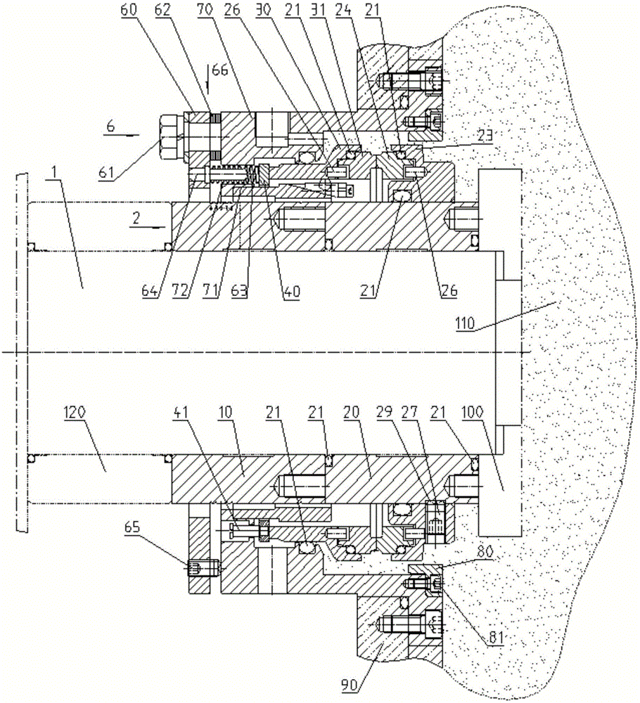
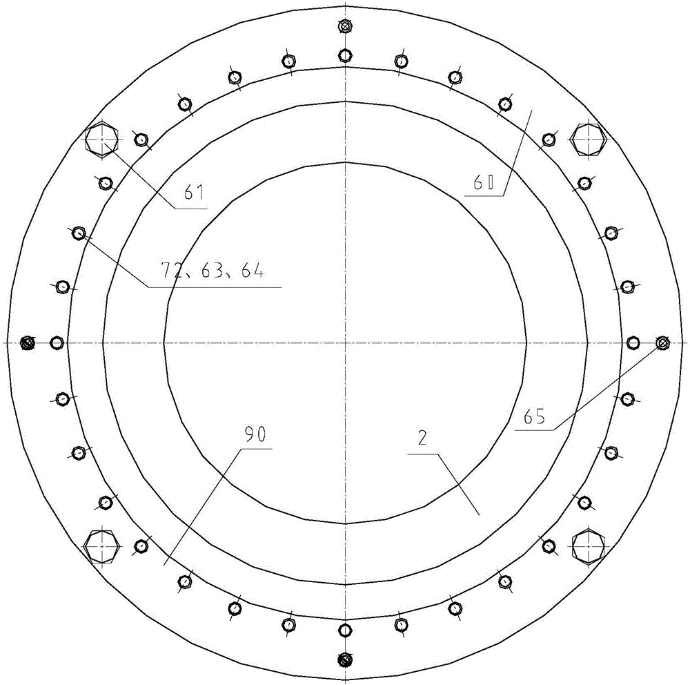
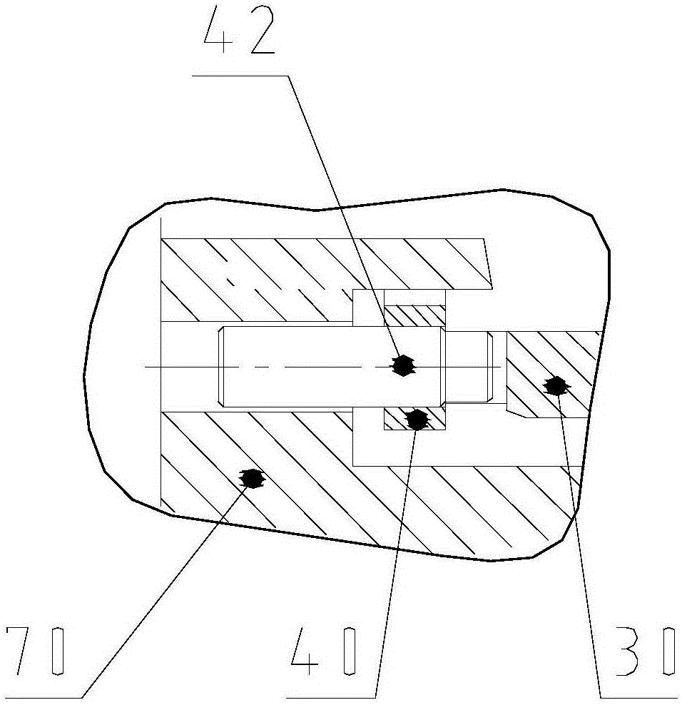
[0030] see Figure 1 to Figure 5 , a mechanical seal device of a large dredger dredger pump with an axial adjustment function, the mechanical seal device is installed on the pump shaft 1 of the dredger inner dredger pump, and includes a seal box 70 sealingly connected with the dredger pump 90, Its main function is to fix the static part of the whole set of mechanical seal with the mud pump 90, so that the static ring 31 will not rotate without the rotation of the moving ring 24; The pump shaft is free from wear and corrosion of external factors, and is used to support and connect other parts of the mechanical seal; the moving ring seat 23 with the moving ring 24 installed in the seal box 70 and the static ring seat 30 with the static ring 31 ...


PUM


Abstract

The invention relates to a mechanical sealing device with an axial adjusting function for a large-sized dredger sludge pump. The mechanical sealing device comprises a seal tank connected with the sludge pump in a sealed mode, as well as a moving ring seat provided with a moving ring and a static ring seat provided with a static ring in the seal tank, wherein a push ring is arranged between the static ring seat and the seal tank; the moving ring seat is in fastened connection with a shaft sleeve via a fastening bolt, and rotates together with a pump shaft; an external adjustable static ring axial compensation mechanism is arranged on the outer end face of the seal tank; the external adjustable static ring axial compensation mechanism comprises a gland arranged at the outer end of the seal tank, and the gland is connected with the outer end face of the seal tank; an adjusting gasket is arranged between the gland and the outer end face of the seal tank; and static ring compensation assemblies are uniformly distributed in the circumferential direction of the outer end face of the seal tank. The mechanical sealing device is used for solving split and integrated mechanical sealing; and the working height of a spring is not changed with the adjustment of a pump body in installation and use processes, and the damaged spring element can be replaced timely without detaching equipment, so that the performance stability and reliability of user equipment are guaranteed, and the service life of the sealing device is prolonged.

Description

technical field [0001] The invention relates to the field of mechanical seals, and more specifically relates to a mechanical seal device for a large-scale dredger dredge pump with an axial adjustment function, which solves the problem that the mechanical seal relies on elastic elements to provide compensation force. Background technique [0002] At present, the pump shaft seal device of large dredgers at home and abroad adopts the L-shaped rubber pad seal device. Its working principle is that the static three L-shaped rubber pads and the rotating shaft sleeve dynamically rub against each other, and high pressure is provided between the L-shaped rubber pad seals. Clean water is used to lubricate and block the pumped medium, and the self-elasticity of the rubber and its attached springs are used to provide wear compensation to achieve the purpose of sealing. See figure 1 . This kind of sealing device is suitable for a narrow range of working conditions, and its service life i...

Claims


Application Information

Patent Timeline
Patent Type & Authority Applications(China)
IPC IPC(8): F04D7/04F04D29/12F04D29/00F04D29/62
CPCF04D7/04F04D29/007F04D29/128F04D29/628
Inventor 于建军
Owner 天津市合润科技有限责任公司
Why Eureka
Try Eureka