
Multifunctional stringing auxiliary device for power distribution line
A technology of power distribution lines and auxiliary devices, which is applied in the direction of overhead lines/cable equipment, etc., and can solve the problems of lowering the quality of wiring construction, slow construction progress, and inconvenience
Patent Information
- Authority / Receiving Office
- CN · China
- Patent Type
- Applications(China)
- Current Assignee / Owner
- Publication Date
- 2017-10-24
- Estimated Expiration
- Not applicable · inactive patent
Smart Images
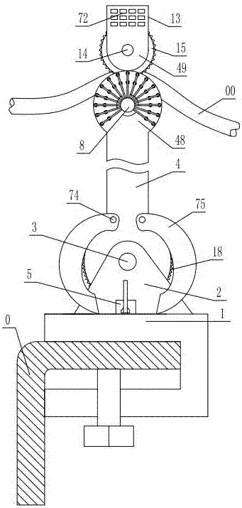
Figure 1 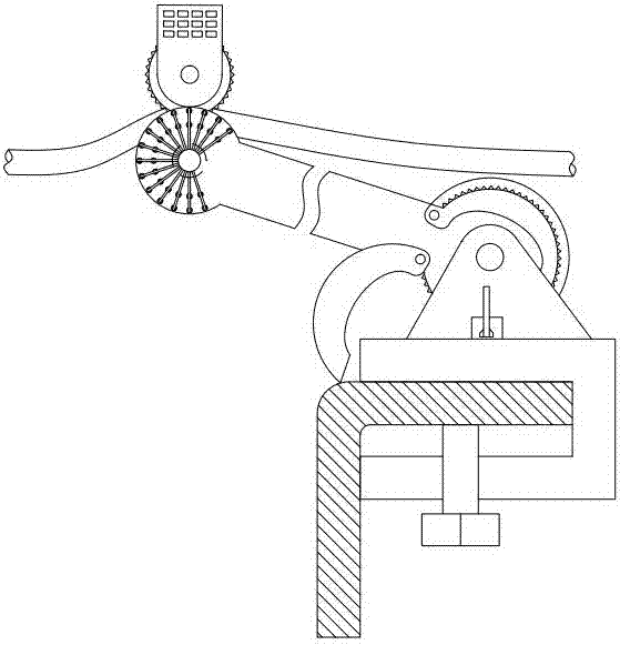
Figure 2 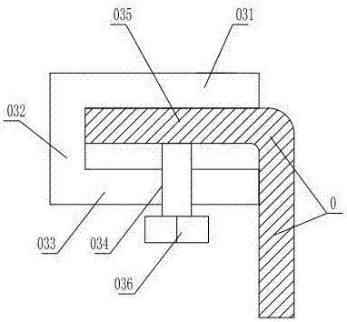
Figure 3
Abstract
Description
technical field
[0001] The invention relates to a multifunctional electric power distribution line stringing auxiliary device. Background technique
[0002] The pay-off block is a tool that must be used in the construction of power lines. The main structure is composed of aluminum or nylon pulleys, frame fixing devices, hooks or U-shaped groove stabilizing devices. Using the pulley during the line erection and tensioning process can reduce the wire Excellent frictional resistance, prevent wire strand damage and insulation layer damage, and can increase construction speed and reduce power outage time.
[0003] Now in the construction of 10kV and below power lines, the distance between the U-shaped groove stabilizer and the top of the pulley is about 140mm for the pay-off tackle used, while the height of the P-15 rod insulator is about 240mm, and the height of the P-20 rod insulator is about 140mm. The height of the insulator is about 350mm, the pulley is short, the insulator...
Examples
Embodiment Construction
[0029]As shown in the figure, the multi-functional power distribution line stringing auxiliary device includes a base 1, and a lower locking device that is locked and matched with the cross arm 0 of the pole is provided at the bottom of the base. 1. The upper plate 031 extending horizontally at the bottom. The rear end of the upper plate 031 is vertically fixed with a vertical plate 032 extending downward. A screw hole 034 is provided, and the screw hole 034 is screwed with a positioning bolt 036 clamping the horizontal plate 035 of the cross arm 0 in the cavity between the upper plate 031 and the lower plate 032, and the base is fixed with a bracket 2, the bracket A support tube 4 is hinged through the support shaft 3, and the lower section of the support tube is fixed with a lower gear 18 coaxially arranged with the support shaft. There are two main struts 6 and auxiliary struts 7 that extend upwards and are arranged in parallel. A main wheel shaft 8 that is parallel to the ...