Gear device making meshed position fully lubricated

A gear and meshing technology, used in mechanical equipment, gear lubrication/cooling, belt/chain/gear, etc., can solve the problems of lubricating oil staying on the tooth groove or tooth profile, reducing the service life of gears, and gear damage, etc. The effect of shortening the repair time, ensuring the lubrication effect and saving the production cost

Inactive Publication Date: 2017-01-25
安鹏鹏
View PDF6 Cites 4 Cited by
  • Summary
  • Abstract
  • Description
  • Claims
  • Application Information

AI Technical Summary

Problems solved by technology

In the process of use, the rotation of the gear is inseparable from lubrication. Insufficient lubrication will cause great damage to the gear and reduce the service life of the gear, especially the gear working in a harsh environment needs to be constantly lubricated to ensure its normal operation.
The existing method of externally adding lubricating oil tends to make the lubricating oil stay on the tooth grooves or tooth profiles, and the meshing parts of the gear teeth will not be lubricated well, and it is easy to wear out

Method used


Image

  • Gear device making meshed position fully lubricated
  • Gear device making meshed position fully lubricated
  • Gear device making meshed position fully lubricated

Examples


Embodiment 1

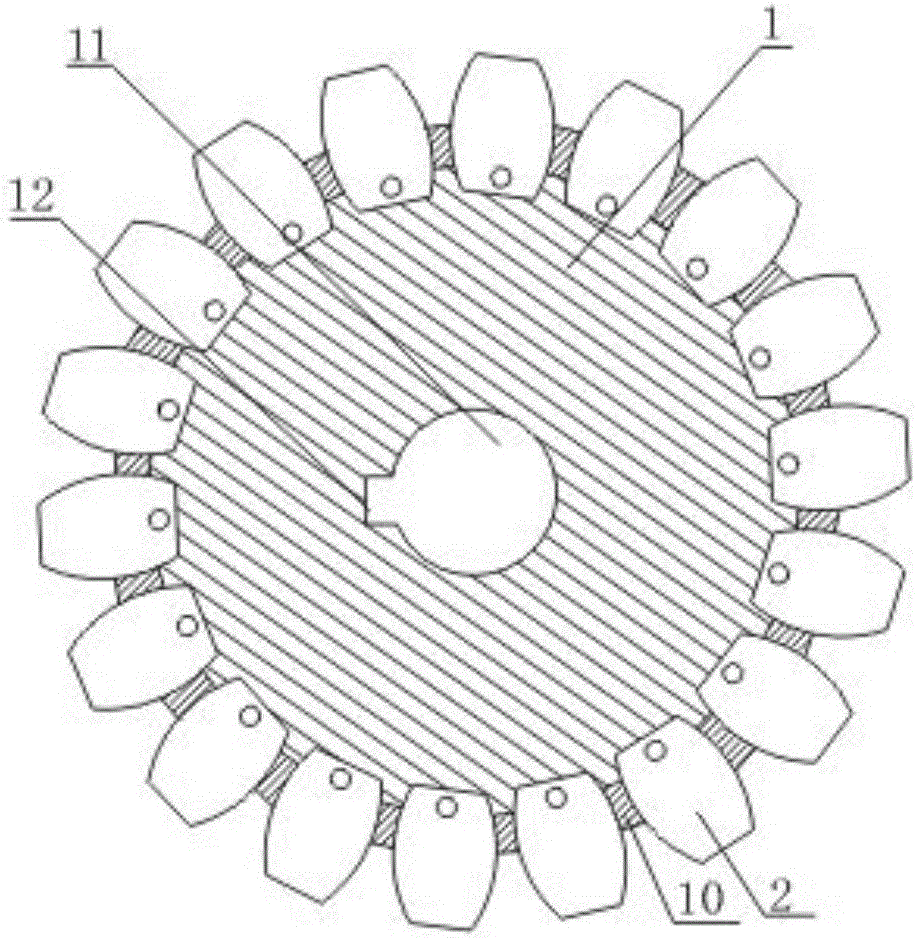
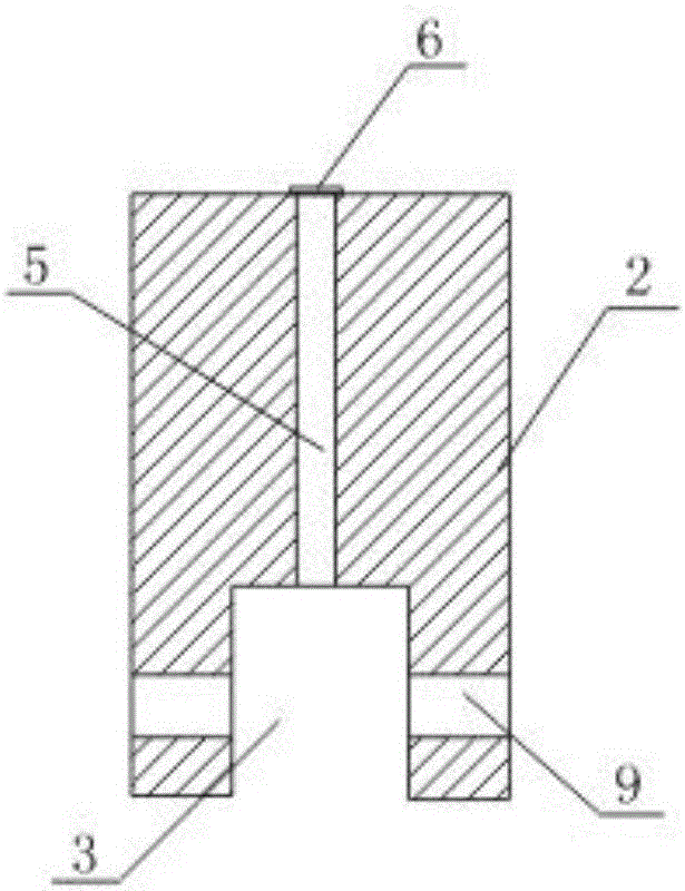
[0030] The gear equipment that is conducive to the full lubrication of the meshing parts includes a gear body 1 and a plurality of gear teeth 2 evenly distributed on the gear body 1. The lower end of the gear teeth 2 is provided with a card slot 3, and the card slot 3 at the lower end of the gear teeth 2 is detachable. The ground is clamped on the gear body 1; the outer wall of the gear body 1 is provided with a lubricating oil receiving groove 4 corresponding to the position where the gear teeth 2 are installed, and the gear teeth 2 are longitudinally provided with an oil guide channel 5 communicating with the card groove 3. The outer end surface of the tooth 2 is provided with a blocking case 6 covering the oil guide passage 5, and an oil outlet hole 7 is opened on the blocking case 6.

Embodiment 2

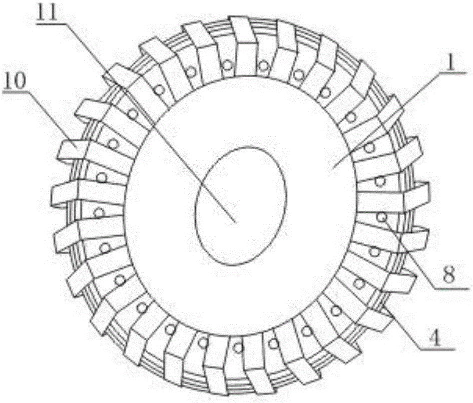
[0032] In this embodiment, on the basis of Embodiment 1, the gear body 1 is provided with a threaded hole A8, and the two sides of the slot 3 at the lower end of the gear teeth 2 are respectively provided with threaded holes B9 matching the threaded hole A8.

Embodiment 3

[0034] In this embodiment, on the basis of embodiment 1 or embodiment 2, several positioning protrusions 10 are evenly arranged on the gear body 1, and the gear teeth 2 are arranged between adjacent positioning protrusions 10, and the positioning protrusions 10 The height is less than the height of the gear tooth 2.


PUM


Abstract

The invention provides a gear device making a meshed position fully lubricated. The gear device comprises a gear body and multiple gear teeth uniformly distributed on the gear body, wherein clamping grooves are formed in the lower ends of the gear teeth, the clamping grooves formed in the lower ends of the gear teeth are detachably clamped on the gear body, a lubricating oil containing groove corresponding to the gear tooth installation position is formed in the outer side wall of the gear body, the gear teeth are longitudinally provided with oil guiding channels communicated with the clamping grooves, the outer end faces of the gear teeth are provided with a blocking housing covering the oil guiding channels, and an oil outlet hole is formed in the blocking housing. Lubricating oil is put in the lubricating oil containing groove, the clamping grooves are provided with the oil guiding channels communicated with the clamping grooves, and the lubricating oil located in the containing groove sequentially passes through the oil guiding channels and the oil outlet hole formed in the blocking housing to flow out. Due to the fact that the oil outlet hole is located in the outer end face of the gear teeth, and lubricating oil fully flows into the meshed positions of the gear teeth to ensure a lubricating effect.

Description

technical field [0001] The invention relates to a gear device, in particular to a gear device which facilitates sufficient lubrication of meshing parts. Background technique [0002] Gear mechanism is the basic element used to realize gear movement and power transmission. Gear mechanism is the most widely used transmission mechanism in modern machinery, which can be used to transmit motion and power between any two axes in space. Compared with other transmission mechanisms, the advantages of the gear mechanism are: compact structure, reliable operation, stable transmission, high efficiency, long life, constant transmission ratio, and large transmission power and applicable speed range. Therefore, gear mechanisms are widely used in mechanical transmission. In the process of use, the rotation of the gear is inseparable from lubrication. Insufficient lubrication will cause great damage to the gear and reduce the service life of the gear, especially the gear working in a harsh...

Claims


Application Information

Patent Timeline
Patent Type & Authority Applications(China)
IPC IPC(8): F16H55/17F16H55/12F16H57/04
CPCF16H55/17F16H55/12F16H57/043F16H2055/175
Inventor 安鹏鹏
Owner 安鹏鹏
Why Eureka
Try Eureka