Quick-replaceable main drive seal structure of shield machine
A sealing structure and main drive technology, applied in the direction of engine sealing, mechanical equipment, engine components, etc., can solve the problems of limited internal space of the equipment, difficult disassembly and installation, high cost investment, shortening maintenance time, shortening maintenance cost, The effect of low cost investment
- Summary
- Abstract
- Description
- Claims
- Application Information
AI Technical Summary
Problems solved by technology
Method used
Image

Examples
Embodiment Construction
[0024] A preferred embodiment of the present invention will be described in detail below in conjunction with the accompanying drawings. However, the scope of protection of the present invention is not limited to the following examples, that is, any simple equivalent changes and modifications made based on the patent scope of the present invention and the content of the description are still within the scope of the patent of the present invention.
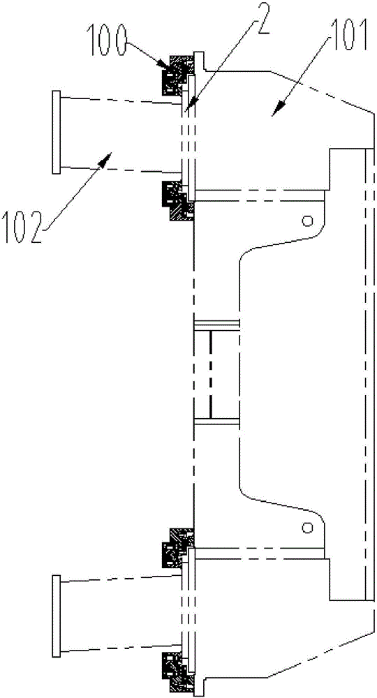
[0025] refer to figure 1 , is a schematic diagram of the installation position of a quickly replaceable shield machine main drive sealing structure described in the present invention, the sealing structure 100 is installed on the cutter head flange connecting the shield machine main drive 101 and the cutter head corbel 102 .
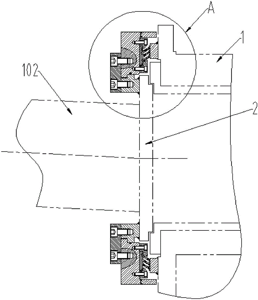
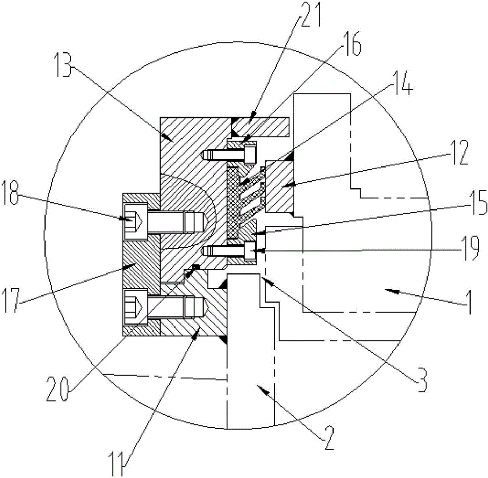
[0026] refer to figure 2 , 3 , is a quick-change shield machine main drive sealing structure described in the present invention, including a main drive frame 1 and a cutter head flange 2 for fixing the shi...
PUM
 Abstract
Description
Claims
Application Information
PatSnap Eureka turns technology decisions into work you can execute. Powered by our Innovation Knowledge Graph, it runs expert workflows across engineering, life sciences, materials and intellectual property. Get your review-ready output in minutes.


