Moving control method of virtual reality
A technology of virtual reality and control method, applied in the field of virtual reality, which can solve problems such as the difference between visual perception and body perception, the perceived information is not synchronized, and users are dizzy, so as to achieve a strong sense of substitution, improve authenticity, and have a large range of movement Effect
- Summary
- Abstract
- Description
- Claims
- Application Information
AI Technical Summary
Problems solved by technology
Method used
Image

Examples
Embodiment 1
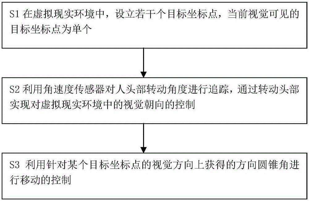
[0048] A mobile control method for virtual reality, said method comprising the following steps:
[0049] S1 In the virtual reality environment, several target coordinate points are set up, and the visually visible target coordinate point is a single one;
[0050] S2 uses the angular velocity sensor to track the rotation angle of the human head, and realizes the control of the visual orientation in the virtual reality environment by turning the head;
[0051] S3 uses the direction cone angle obtained in the visual direction for a certain target coordinate point to control the movement.
[0052] The control of movement refers to accelerating forward, running at a constant speed, and decelerating to stop. The setting of the target coordinate point can be a specific point or line segment or a surface with a boundary.
Embodiment 2
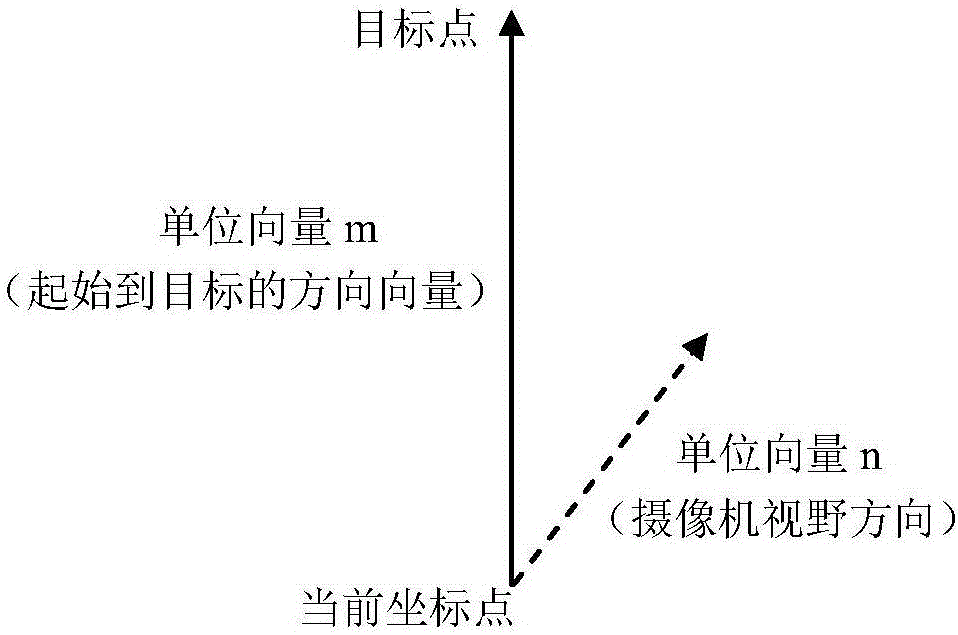
[0054] As a specific or preferred version of embodiment 1. The process of obtaining the direction cone angle in step 3 is to monitor the displayed screen frame by frame of the user's visual orientation, on the line between the user's current coordinate point and the target coordinate point, that is, the direction toward the target coordinate point Direction, set the direction cone angle, the apex of the cone is the user's current coordinate point, and the bottom surface faces the target coordinate point.
[0055] Such as image 3 As shown, when the visual orientation deviates from the target coordinate point, m is the unit vector in the direction from the user's current coordinate point to the target coordinate point, n is the unit vector in the visual orientation direction, and the direction cone angle is defined by m and n. When If the direction cone angle is m n > 0.6, it means that the user continues to move towards the target point, so he continues to walk at the current...
Embodiment 3
[0058] As an embodiment of embodiment 1 or 2, step S3 in embodiment 1 includes the following steps:
[0059] A is determined to move to a certain target coordinate point;
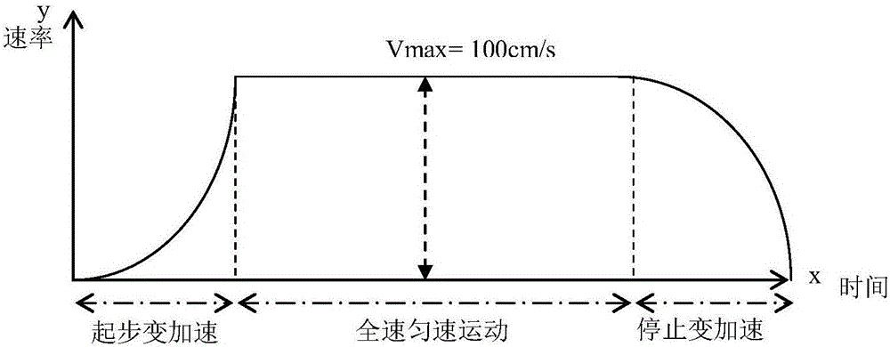
[0060] B The user starts to move, accelerates according to the preset first acceleration curve, and the acceleration increases with time until the speed reaches the preset maximum speed value, and then moves at a constant speed according to the preset maximum speed value;
[0061] C When the distance between the user's current location point and the target coordinate point is less than the preset distance value, use the preset first deceleration curve to decelerate. The deceleration speed increases with time, and the speed drops to zero at the same time. or reach the target coordinate point.
[0062] In order to illustrate the change of moving speed more clearly, the following is combined with the attached figure 2 Be specific. For example, when the user moves from the current coordinate point to the ta...
PUM
 Abstract
Description
Claims
Application Information
 - R&D
- Intellectual Property
- Life Sciences
- Materials
- Tech Scout
- Unparalleled Data Quality
- Higher Quality Content
- 60% Fewer Hallucinations
Browse by: Latest US Patents, China's latest patents, Technical Efficacy Thesaurus, Application Domain, Technology Topic, Popular Technical Reports.
© 2025 PatSnap. All rights reserved.Legal|Privacy policy|Modern Slavery Act Transparency Statement|Sitemap|About US| Contact US: help@patsnap.com