
A reactive power compensation regulator, device and system for power distribution system

A compensation device and power distribution system technology, applied in reactive power compensation, reactive power adjustment/elimination/compensation, circuit devices, etc., can solve problems such as large inrush current, complex and uncertain power grid harmonics, and easy damage to thyristors.

Inactive Publication Date: 2019-01-01
GUANGDONG UNIV OF TECH
View PDF4 Cites 0 Cited by
  • Summary
  • Abstract
  • Description
  • Claims
  • Application Information

AI Technical Summary

Problems solved by technology

However, although the bidirectional thyristor driver MOC3083 can accurately trigger the thyristor into the capacitor bank at the zero-crossing point under the normal theoretical conditions of the power grid, in the actual distribution network, due to the complex and uncertain harmonics of the power grid, especially when the grid voltage is distorted, light Coupling is prone to misoperation
As a result, the capacitor bank may not be put into the power grid at the zero crossing point, resulting in excessive surge current, which is easy to damage the thyristor, and even some capacitor banks can be found to explode directly at the scene.

Method used


Image

  • A reactive power compensation regulator, device and system for power distribution system
  • A reactive power compensation regulator, device and system for power distribution system
  • A reactive power compensation regulator, device and system for power distribution system

Examples


Embodiment Construction

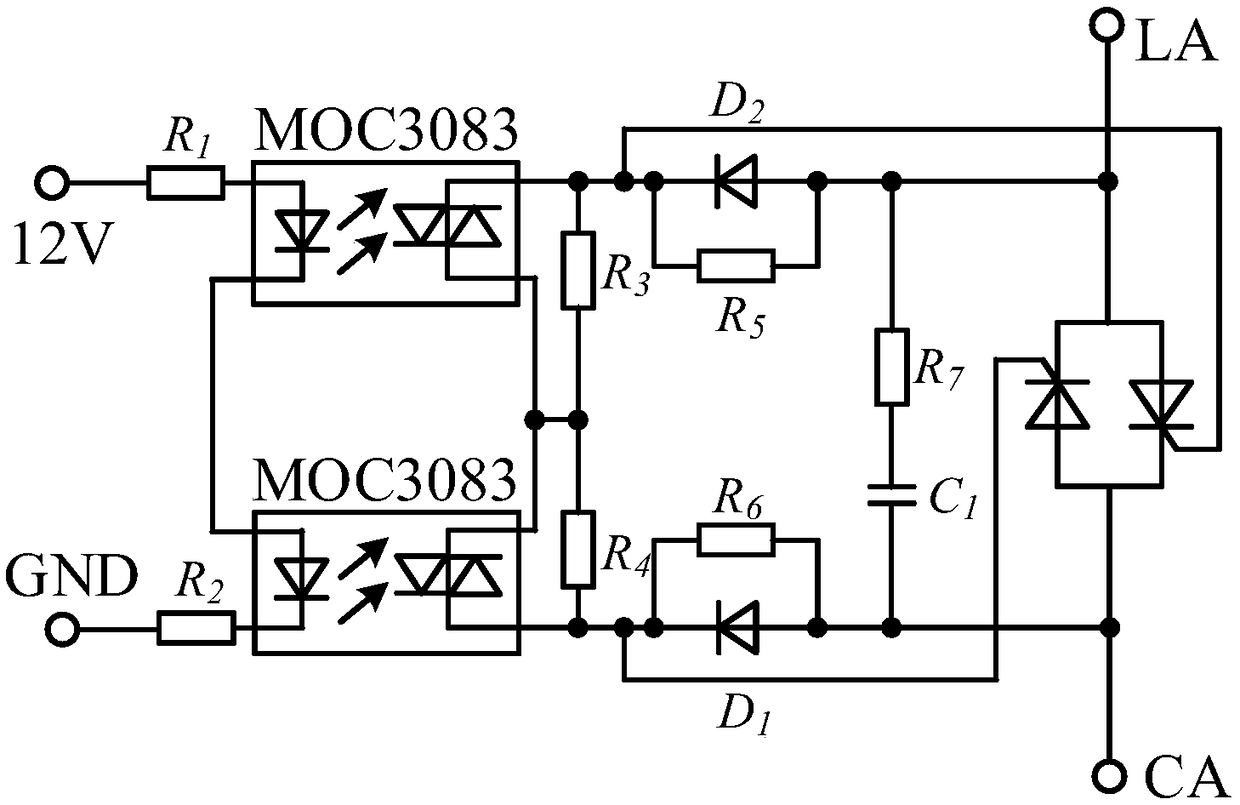
[0033]The core of the present invention is to provide a reactive power compensation regulator for power distribution system, which effectively avoids the malfunction of the first optocoupler and causes the capacitor bank to be put into the power grid when it is not at the zero crossing point, and improves the safety performance; Another core of the present invention is to provide a reactive power compensation device and system including the above reactive power compensation regulator for power distribution system.

[0034] In order to make the purpose, technical solutions and advantages of the embodiments of the present invention clearer, the technical solutions in the embodiments of the present invention will be clearly and completely described below in conjunction with the drawings in the embodiments of the present invention. Obviously, the described embodiments It is a part of embodiments of the present invention, but not all embodiments. Based on the embodiments of the pre...


PUM


Abstract

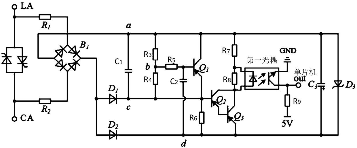
The invention discloses a reactive compensation regulator for a power distribution system, a device and a system. The reactive compensation regulator for the power distribution system comprises a zero cross direction circuit. The zero cross direction circuit comprises two anti-parallel single-phase silicon controlled rectifiers of which the first common terminal is connected with a grid and the second common terminal is connected with a capacitor, a rectifier bridge, a first diode, a second diode, a first voltage stabilization capacitor, a second voltage stabilization capacitor, a clamping capacitor, a first divider resistor, a second divider resistor, a first PNP, a second PNP, a third PNP, a first current-limiting resistor, a second current-limiting resistor, a third current-limiting resistor, a fourth current-limiting resistor, a voltage-regulator tube, a first discharge resistor, a second discharge resistor and a first optical coupler. The output terminal of the first optical coupler is used as the output terminal, connected with a single-chip, of the zero cross detection circuit. The reactive compensation regulator for the power distribution system is capable of effectively avoiding the situation that the capacitor bank is put into the grid away from the zero crossing point because of the misoperation of the first optical coupler, and improving the safety performance.

Description

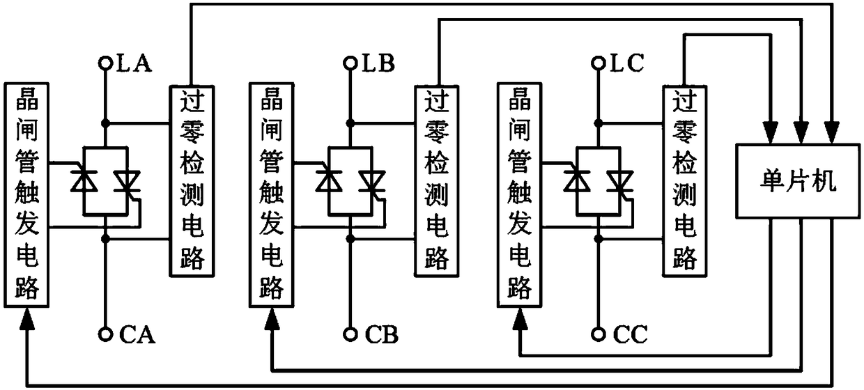
technical field [0001] The invention relates to the technical field of reactive power compensation, in particular to a reactive power compensation regulator, device and system for power distribution systems. Background technique [0002] At present, in the low-voltage distribution network, TSC (Thyristor switched capacitor) is widely used as a low-voltage reactive power compensation device due to its low price, convenient maintenance, easy expansion, and small footprint. The low-voltage reactive power compensation device includes a main controller, a reactive power compensation regulator and a capacitor bank, wherein the reactive power compensation regulator includes a single-chip microcomputer, 3 groups of zero-crossing detection circuits corresponding to the three-phase AC circuit and a thyristor drive circuit. When the single-chip microcomputer receives the capacitor input command sent by the main controller, and when the zero-crossing detection circuit detects that the g...

Claims


Application Information

Patent Timeline
Patent Type & Authority Patents(China)
IPC IPC(8): H02J3/18H02J3/01
CPCH02J3/01H02J3/1821Y02E40/30Y02E40/40
Inventor 彭洁锋程汉湘阳海彪方伟明
Owner GUANGDONG UNIV OF TECH
Learn More