Stator machining method and device and rotor machining method and device

A processing equipment and processing method technology, applied in the direction of metal processing equipment, turning equipment, turning equipment, etc., can solve the problems of complex processing technology, difficult processing, high cost, etc., and achieve wide application range, short processing cycle and low production cost Effect

Active Publication Date: 2017-02-01
SOUTH CHINA UNIV OF TECH +2
View PDF11 Cites 4 Cited by
  • Summary
  • Abstract
  • Description
  • Claims
  • Application Information

AI Technical Summary

Problems solved by technology

[0007] Another object of the present invention is to provide a special rotor processing method for the screw rotor volume transport equipment. This method utilizes the principle of relative motion between the sta

Method used


Image

  • Stator machining method and device and rotor machining method and device
  • Stator machining method and device and rotor machining method and device
  • Stator machining method and device and rotor machining method and device

Examples


Embodiment 1

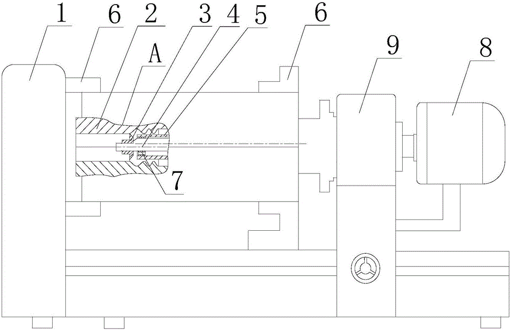
[0032]This embodiment is a stator processing method. Using the principle of relative motion between the stator and the rotor, the rotor is made into a stator tool, and the inner cavity of the stator is cut through the stator tool. The driving device of the stator tool is an autorotation and revolution drive with a feeding function. The device makes the stator tool not only rotate around the axis of the stator tool itself, but also perform revolution around the axis of the stator during the feed movement.

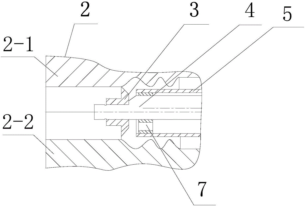
[0033] A stator processing equipment for realizing the above method, such as figure 1 As shown, it includes machine tool 1, rotation and revolution drive device, stator 2, stator cutter 3, stator cutter drive rod 4 and stator cutter support sleeve 5, the rotation and revolution drive device is arranged on the machine tool, and the two ends of the stator pass through the chuck 6 and the machine tool respectively. connection, the stator cutter is set in the inner cavity of the...

Embodiment 2

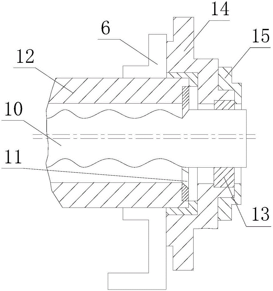
[0038] This embodiment is a rotor processing method, using the principle of relative motion between the stator and the rotor, the stator is made into a rotor tool, and the outer periphery of the rotor is cut through the rotor tool, and the driving device of the rotor is an autorotation and revolution driving device with a feeding function. In the process of feeding the rotor, the rotor not only rotates around the axis of the rotor itself, but also revolves around the axis of the rotor cutter.

[0039] A rotor processing equipment for realizing the above method, such as image 3 As shown, it includes a machine tool, an autorotation and revolution driving device, a rotor 10, a rotor tool 11 and a rotor tool driving sleeve 12. The autorotation and revolution driving device is arranged on the machine tool, and the two ends of the rotor tool driving sleeve are respectively connected to the machine tool through chucks 6. The rotor tool A rotor cutter is installed on the inner wall o...


PUM


Abstract

The invention discloses a stator machining method and device and a rotor machining method and device. The relative movement principle of a stator and a rotor is utilized, during stator machining, the rotor is manufactured to a stator tool which is used for cutting an inner cavity of the stator, and a driving device of the stator tool is a rotation-revolution driving device with a feeding function, so that the stator tool rotates around the axis of the stator tool and does revolution movement around the axis of the stator in the tool feeding movement process; and during rotor machining, the stator is manufactured to a rotor tool which is used for cutting the periphery of the rotor, and a driving device of the rotor is a rotation-revolution driving device with a feeding function, so that the rotor rotates around the axis of the rotor and does revolution movement around the axis of the rotor tool in the feeding movement process. By means of the stator machining method and device and the rotor machining method and device, the problems that traditional machining processes are complex, the machining difficulty is high, the cycle is long, and the cost is high are effectively solved.

Description

technical field [0001] The invention relates to the technical field of mechanical processing, in particular to a stator processing method and equipment for a helical rotor volume transport device, and a rotor processing method and equipment. Background technique [0002] Screw rotor volume transport equipment has a very wide range of applications in the field of mechanical engineering involving fluid transport. For example, in the field of polymer material processing machinery, some plasticizing transport devices use the rotor to rotate eccentrically around the stator and rotate in reverse at a constant speed The movement makes the closed cavity formed by the rotor and the stator move axially to realize the suction, extrusion and discharge of the melt; in the field of petrochemical industry, the fluid conveying machinery mostly adopts the positive displacement pump structure, which utilizes the rotation of the rotor in the inner cavity of the stator and revolution motion to ...

Claims


Application Information

Patent Timeline
IPC IPC(8): B23B5/00B23B1/00B23B15/00
CPCB23B1/00B23B5/00B23Q7/00B23Q2707/003
Inventor 瞿金平
Owner SOUTH CHINA UNIV OF TECH
Why Eureka
Try Eureka