Silicon wafer cutting machine used for silicon solar energy production

A technology of solar energy and cutting machine, applied in the direction of fine working devices, working accessories, grain processing, etc., can solve the problems of uneven cutting, slow cutting speed, incomplete cutting, etc., and achieve the effect of flexible swing and long service life

Inactive Publication Date: 2017-02-01
WUXI YANAO ELECTRONICS TECH
View PDF6 Cites 11 Cited by
  • Summary
  • Abstract
  • Description
  • Claims
  • Application Information

AI Technical Summary

Problems solved by technology

[0006] In order to overcome the disadvantages of slow cutting speed, uneven cutting and incomplete cutting in the existing silicon wafer cutting machine, the technical problem to be solved by the present invention is to provide a silicon solar energy production method with fast cutting speed, uniform cutting and thorough cutting. Wafer cutting machine

Method used


Image

  • Silicon wafer cutting machine used for silicon solar energy production
  • Silicon wafer cutting machine used for silicon solar energy production
  • Silicon wafer cutting machine used for silicon solar energy production

Examples


Embodiment 1

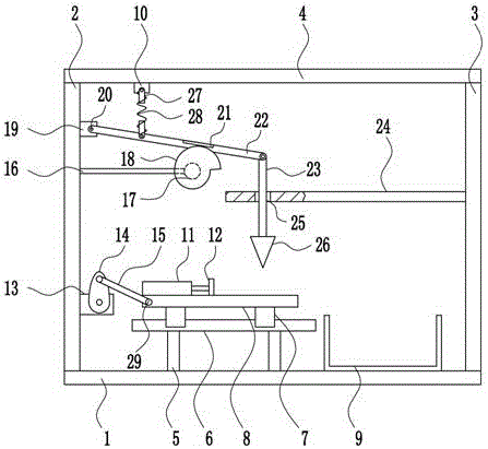
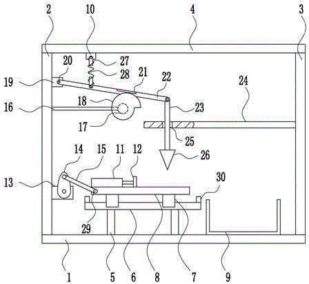
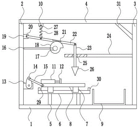
[0034] A silicon wafer cutting machine for silicon solar energy production, such as Figure 1-5 As shown, it includes bottom plate 1, left frame 2, right frame 3, top plate 4, first pole 5, slide rail 6, slider 7, cutting plate 8, collection frame 9, first fixed block 10, electric push rod 11. Push plate 12, first motor 13, crank 14, connecting rod 15, second pole 16, second motor 17, latch cam 18, second fixed block 19, first hinged part 20, block 21, swing Rod 22, lifting rod 23, guide plate 24, cutter 26, fixed rod 27, spring 28 and second hinged part 29, left frame 2 is welded on the left end of bottom plate 1 top, and left frame 2 right upper part is connected by the mode of bolt connection There is a second fixed block 19, the front side of the second fixed block 19 is connected with a swing rod 22 through the first hinge part 20, the right part of the front side of the swing rod 22 is connected with a stopper 21 by means of bolt connection, and the right end of the swin...


PUM


Abstract

The invention relates to a silicon wafer cutting machine, in particular to a silicon wafer cutting machine used for silicon solar energy production. The silicon wafer cutting machine used for silicon solar energy production is high in cutting speed and even and thorough in cutting. The silicon wafer cutting machine used for silicon solar energy production comprises a bottom plate, a left frame, a right frame, a top plate, a first support rod, a sliding rail, sliding blocks, a cutting plate, a collecting frame, a first fixing block, an electric pushing rod, a pushing plate, a first motor and others; the left frame is welded to the left end of the top of the bottom plate, a second fixing block is connected to the upper portion of the right side of the left frame through a bolt, and a swinging rod is connected to the front side of the second fixing block through a first hinged component. According to the embodiment, only the preferable implementation mode is expressed, the embodiment has detailed description, but it shall not be understood that the silicon wafer cutting machine is limited to the range which the embodiment is implemented in.

Description

technical field [0001] The invention relates to a silicon wafer cutting machine, in particular to a silicon wafer cutting machine for silicon solar energy production. Background technique [0002] Solar energy refers to the thermal radiation energy of the sun, and its main manifestation is the sun's rays that are often said. In modern times, it is generally used to generate electricity or provide energy for water heaters. Since the birth of life on earth, it has mainly survived on the heat radiation energy provided by the sun. Since ancient times, humans have also known to use sunlight to dry objects and use it as a method of making food, such as making salt and drying salted fish. With fossil fuels decreasing day by day, solar energy has become an important part of the energy used by human beings and has been continuously developed. There are two ways to use solar energy: photothermal conversion and photoelectric conversion. Solar power is a new type of renewable energy. ...

Claims


Application Information

Patent Timeline
Patent Type & Authority Applications(China)
IPC IPC(8): B28D5/04B28D7/00B02C18/02B02C18/04
CPCB28D5/04B02C18/02B02C18/04B28D5/0058B28D5/0064
Inventor 陈敏华唐余武
Owner WUXI YANAO ELECTRONICS TECH
Why Eureka
Try Eureka