A pad printing coding device

A pad printing and equipment technology, applied in printing, printing presses, rotary printing presses, etc., can solve the problems of low pad printing efficiency, poor pad printing definition, unreasonable structure design, etc., and achieve the effect of improving production efficiency

Active Publication Date: 2018-11-27
CHENGDU OJA AIRCRAFT CABIN EQUIP
View PDF9 Cites 0 Cited by
  • Summary
  • Abstract
  • Description
  • Claims
  • Application Information

AI Technical Summary

Problems solved by technology

In the pad printing machine disclosed in this patent document, the pad printing rubber head and the oil cup work independently of each other. Although it can avoid the waste of energy consumption caused by the movement of the oil cup and the pad printing rubber head moving together, due to the unreasonable structural design, there are also problems with the pad printing. Problems with poor printing clarity and low pad printing efficiency

Method used


Image

  • A pad printing coding device
  • A pad printing coding device
  • A pad printing coding device

Examples


Embodiment 1

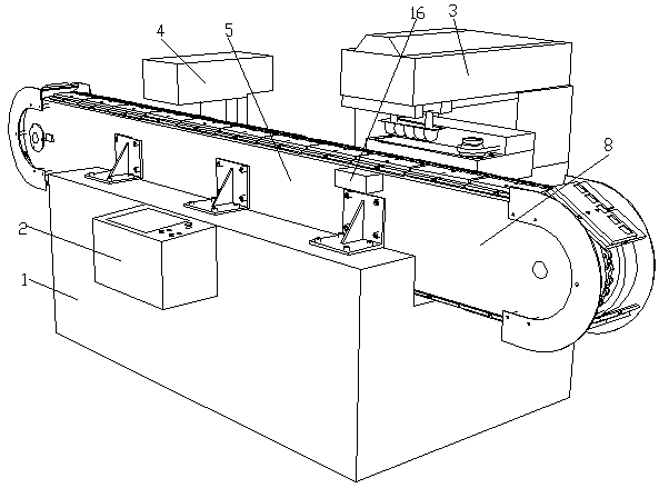
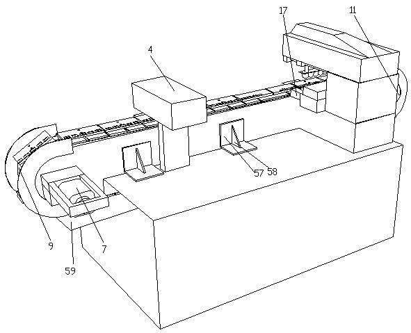
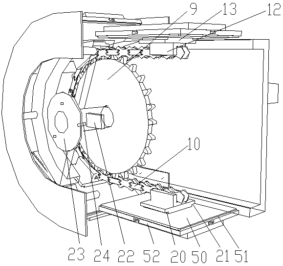
[0041] A pad printing and coding equipment, including a workbench 1, a PLC controller 2 and a pad printer 3 arranged on the workbench 1, and a laser coding machine 4 and a conveying part 5 arranged on the workbench 1, so The conveying part 5 includes a motor 7, a transmission case 8 and a main sprocket 9, a chain 10 and a secondary sprocket 11 located in the transmission case 8, the main sprocket 9 is connected with the motor 7, and the secondary sprocket 11 is connected to the main chain through the chain 10 The wheel 9 is connected by transmission. The chain 10 is fixed with a plurality of fixed seats 12, the fixed seats 12 are connected with a positioning block 13, the positioning block 13 is connected with a bracket 14, and the bracket 14 is provided with a mold groove 15. The bracket 14 is located on the surface of the transmission box 8; the side wall of the transmission box 8 is provided with a pad printing positioning piece, and the pad printing positioning piece includ...

Embodiment 2

[0044] A pad printing and coding equipment, including a workbench 1, a PLC controller 2 and a pad printer 3 arranged on the workbench 1, and a laser coding machine 4 and a conveying part 5 arranged on the workbench 1, so The conveying part 5 includes a motor 7, a transmission case 8 and a main sprocket 9, a chain 10 and a secondary sprocket 11 located in the transmission case 8, the main sprocket 9 is connected with the motor 7, and the secondary sprocket 11 is connected to the main chain through the chain 10 The wheel 9 is connected by transmission. The chain 10 is fixed with a plurality of fixed seats 12, the fixed seats 12 are connected with a positioning block 13, the positioning block 13 is connected with a bracket 14, and the bracket 14 is provided with a mold groove 15. The bracket 14 is located on the surface of the transmission box 8; the side wall of the transmission box 8 is provided with a pad printing positioning piece, and the pad printing positioning piece includ...

Embodiment 3

[0050] A pad printing and coding equipment, including a workbench 1, a PLC controller 2 and a pad printer 3 arranged on the workbench 1, and a laser coding machine 4 and a conveying part 5 arranged on the workbench 1, so The conveying part 5 includes a motor 7, a transmission case 8 and a main sprocket 9, a chain 10 and a secondary sprocket 11 located in the transmission case 8, the main sprocket 9 is connected with the motor 7, and the secondary sprocket 11 is connected to the main chain through the chain 10 The wheel 9 is connected by transmission. The chain 10 is fixed with a plurality of fixed seats 12, the fixed seats 12 are connected with a positioning block 13, the positioning block 13 is connected with a bracket 14, and the bracket 14 is provided with a mold groove 15. The bracket 14 is located on the surface of the transmission box 8; the side wall of the transmission box 8 is provided with a pad printing positioning piece, and the pad printing positioning piece includ...


PUM


Abstract

The invention discloses transfer printing and coding equipment which comprises a workbench, a PLC and a transfer printer, and further comprises a laser coding machine and a conveying component. The conveying component comprises a motor, a transmission case, a main chain wheel, a chain and an auxiliary chain wheel. Multiple fixing bases are fixed to the chain and connected with positioning blocks. A bracket is connected to the positioning blocks and provided with die grooves. The side wall of the transmission case is provided with a transfer printing positioning part. One end of the transmission case is provided with an infrared sensor. A motor shaft of the motor is sleeved with a wheel disc. Three sensing columns are distributed on the wheel disc. The infrared sensor, the transfer printer and the laser coding machine are electrically connected with the PLC. By means of organic combination of transfer printing and coding, continuous transfer printing and coding operation of large batches of printed products is achieved, the production efficiency is greatly improved, transfer printing and coding are clearer, and the finesses degree is higher.

Description

technical field [0001] The present invention relates to the technical field of printing equipment, in particular to pad printing coding equipment. Background technique [0002] Pad printing machine is a kind of printing equipment, which is suitable for printing plastic, toys, glass, metal and ceramics. Pad printing is an indirect intaglio printing technology, which has become a main method for surface printing and decoration of various objects. The whole pad printing process mainly includes several steps of inking, ink scraping, ink dipping and pad printing. First, the ink is sprayed on the etching board, and then the excess ink is scraped off with a retractable scraper; The solvent in the ink in the etching area volatilizes and forms a gel-like surface, and then the glue head descends to the etching plate to absorb ink; the glue head absorbs most of the ink on the etching plate and then rises, at this time, this layer of ink volatilizes again One part, the remaining part ...

Claims


Application Information

Patent Timeline
Patent Type & Authority Patents(China)
IPC IPC(8): B41F17/00B41F19/00B41F33/00B41F23/04
CPCB41F17/001B41F19/007B41F23/0466B41F33/0009B41P2200/31
Inventor 项林南
Owner CHENGDU OJA AIRCRAFT CABIN EQUIP
Why Eureka
Try Eureka