
A printing machine control system

A control system and iron printing machine technology, applied in printing machines, general parts of printing machinery, printing, etc., can solve problems such as weak anti-interference ability, low precision, and reduced production efficiency, so as to improve anti-interference ability and improve operation. Speed, the effect of eliminating accumulated errors

Active Publication Date: 2018-07-10
PHASE MOTION CONTROL SOLUTION WUHAN CO LTD
View PDF10 Cites 0 Cited by
  • Summary
  • Abstract
  • Description
  • Claims
  • Application Information

AI Technical Summary

Problems solved by technology

[0003] 1. The frequency converter plus asynchronous motor was used before, the precision is not high, and errors may occur;
[0004] 2. The synchronous zero point of the control system is adjusted manually. After the zero point adjustment of all units is completed, it will start automatic operation. If there is a deviation in the site environment or installation position, it needs to be re-adjusted, which will seriously affect the production progress and reduce the production efficiency. Moreover, the debugging accuracy of artificial debugging cannot reach the best effect, which affects the printing accuracy;
[0005] 3. The driving speed of the driver is controlled by the frequency and number of pulses sent, and the anti-interference ability is weak;
[0006] 4. Each printing iron unit relies on external auxiliary input to maintain synchronization, and the system speed cannot be very high

Method used


Image

  • A printing machine control system

Examples


Embodiment Construction

[0035] The principles and features of the present invention are described below in conjunction with the accompanying drawings, and the examples given are only used to explain the present invention, and are not intended to limit the scope of the present invention.

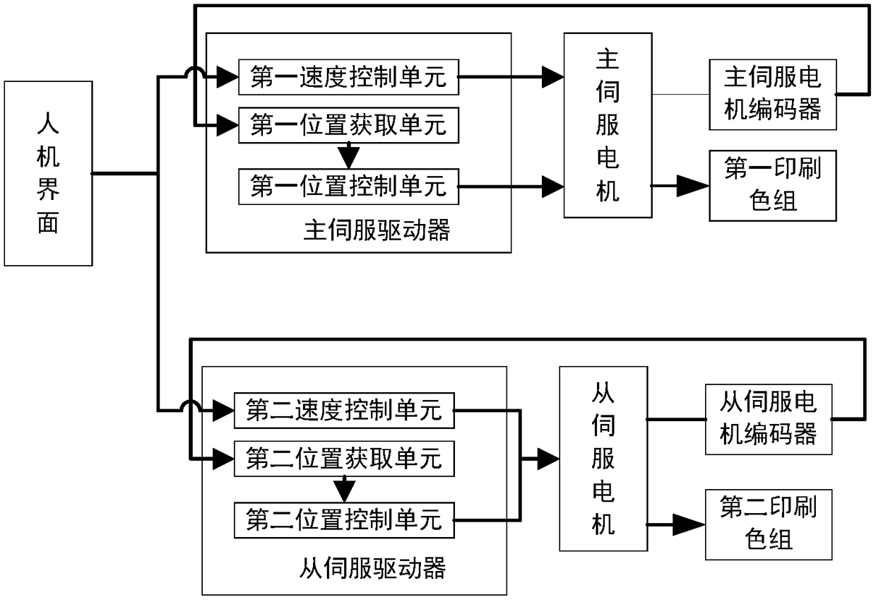
[0036] In Embodiment 1, a two-color iron printing machine is taken as an example to illustrate the control system of the iron printing machine, and the multi-color iron printing machines in other embodiments may be modified by referring to this embodiment. like figure 1 As shown, it is a schematic structural diagram of a two-color iron printing control system in this embodiment, including a man-machine interface, a main motor servo unit and a slave motor servo unit. Drive the corresponding printing color group. The master motor drive unit includes a master servo driver and a master servo motor, and the slave motor servo unit includes a slave servo driver and a slave servo motor. The second printing color group is ...


PUM


Abstract

The invention relates to the field of printing, in particular to a metal decorating machine control system. According to the technical scheme, a logic controller is eliminated, servo drivers realize synchronization of the printing process through the control mode of combining the circulation speed mode and the closed position loop mode directly, the printing accuracy is improved, and the system operation speed is increased; and the zero point of each printing color unit servo motor is corrected through the automatic zero point compensation mode, the zero point correction speed is increased, the zero point correction accuracy is improved, the printing speed is increased, and the printing accuracy is improved.

Description

technical field [0001] The invention relates to the field of printing, in particular to a control system for an iron printing machine. Background technique [0002] Iron printing technology is to print the ink to be printed on the iron plate through various water rollers, ink rollers, rubber rollers and other mechanisms. Generally, there are single-color units, two-color units, three-color units, and four-color units. The whole system includes feeding, mimeograph, feeding and other stations. Since the multi-color iron printing unit needs to print multiple times on the same iron plate, it is necessary to ensure the synchronization of feeding when entering each printing station, otherwise it is easy to damage the product. The problem. There are following problems in the scheme of prior art: [0003] 1. The frequency converter plus asynchronous motor was used before, the precision is not high, and errors may occur; [0004] 2. The synchronous zero point of the control system...

Claims


Application Information

Patent Timeline
Patent Type & Authority Patents(China)
IPC IPC(8): B41F33/16
CPCB41F33/16
Inventor 杜佳成夏风陈宗雨杨合跃贺东升
Owner PHASE MOTION CONTROL SOLUTION WUHAN CO LTD
Learn More