
Two-wheel differential motion robot chassis

A robot and chassis technology, applied in the field of robot research and development, can solve the problems such as the inability to install the structural suspension mechanism and the small remaining space of the chassis, and achieve the effects of optimal suspension, less chassis space occupation, and scientific and reasonable structural design.

Inactive Publication Date: 2017-02-01
浙江众导机器人科技有限公司
View PDF7 Cites 1 Cited by
  • Summary
  • Abstract
  • Description
  • Claims
  • Application Information

AI Technical Summary

Problems solved by technology

[0002] Generally speaking, people in the industry know that the driving wheels of the chassis of a two-wheel differential robot must have a suspension structure. However, when the chassis of the robot is reduced to a certain size, the remaining space of the chassis is very small, and it is impossible to install a suspension with a more complex structure. mechanism

Method used


Image

  • Two-wheel differential motion robot chassis
  • Two-wheel differential motion robot chassis
  • Two-wheel differential motion robot chassis

Examples


Embodiment Construction

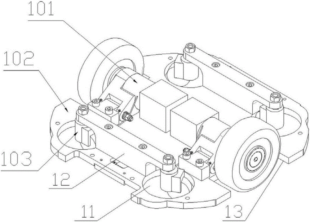
[0035] see figure 1 , with reference to Figure 2-Figure 9 , shown in the figure is a two-wheel differential robot chassis involved in the present invention, and the key technical solutions adopted are as follows:

[0036] As shown in the figure, the chassis involved in the present invention mainly includes a bottom plate 102, on which a pair of suspension mechanisms 101 are fixedly connected with the bottom plate 102 through connecting pieces.

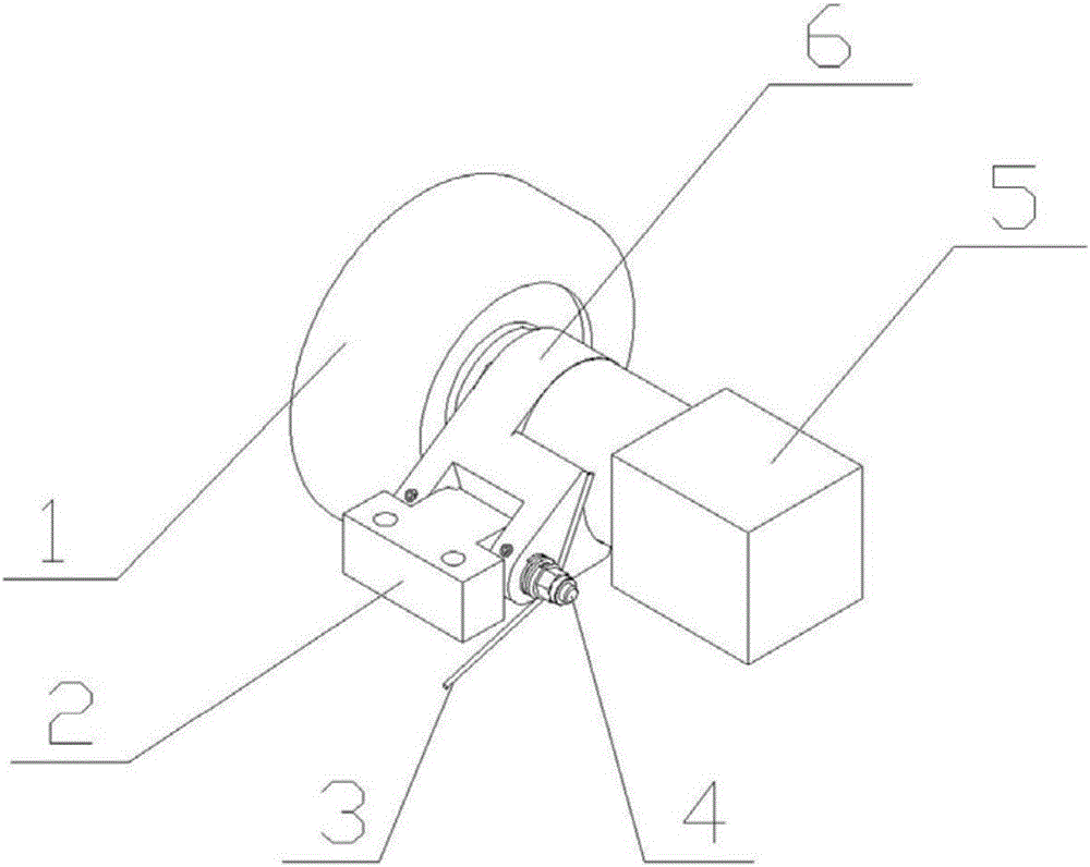
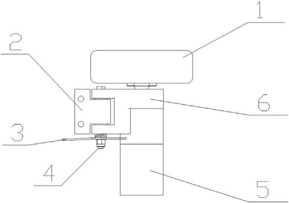
[0037] Suspension mechanism 101 comprises a suspension bracket 6, the driving wheel 1 that is movably connected with this suspension bracket 6, and the drive motor 5 that adopts direct connection mode to be connected with driving wheel 1; The suspension bracket 6 is provided with a rotating shaft parallel to the output shaft of the motor 4. The rotating shaft 4 is pierced with a suspension mount 2 fixedly connected to the bottom plate 102; the extended end of the rotating shaft 4 is provided with a torsion spring 3, and one end of th...


PUM


Abstract

A two-wheel differential motion robot chassis comprises a bottom plate, and a pair of suspension mechanisms is arranged on the bottom plate. Each suspension mechanism comprises a suspension supporting frame, a driving wheel movably connected with the supporting frame and a motor directly connected with the driving wheel, wherein the suspension supporting frame is provided with a rotary shaft parallel to an output shaft of the motor; the rotary shaft is provided with a suspension fixing seat fixedly connected with the bottom plate in a penetrating mode; a torsion spring is arranged at the extension end of the rotary shaft, one end of the torsion spring is pressed on the motor, and the other end of the torsion spring is pressed on the bottom plate and forms pretightening force between the motor and the bottom plate; the bottom plate is provided with a pair of opening grooves where the driving wheel can move; and the suspension mechanism swings up and down around the rotary shaft overall. The four corners of the bottom plate are provided with round holes, and a universal wheel is movably arranged in each hole. A universal wheel supporting frame is arranged on the part, between the round holes on the left side, of the bottom plate, and a universal wheel supporting frame is arranged on the part, between the round holes on the right side, of the bottom plate. Wheel axles of the two universal wheels on each side are fixedly connected at the two ends of the corresponding supporting frame.. Each suspension mechanism is of a structure with the rotary center parallel to a motor shaft, so that the structure size of the chassis is further reduced, and the chassis can smoothly pass through uneven road surfaces.

Description

technical field [0001] The invention belongs to the technical field of robot research and development, and relates to a robot chassis, in particular to a two-wheel differential robot chassis. Background technique [0002] Generally speaking, people in the industry know that the driving wheels of the chassis of a two-wheel differential robot must have a suspension structure. However, when the chassis of the robot is reduced to a certain size, the remaining space of the chassis is very small, and it is impossible to install a suspension with a more complex structure. mechanism. [0003] Therefore, how to design a suspension mechanism with a reasonable structure and how to install it on the robot chassis with a small space, while ensuring that the robot chassis can pass through smoothly when the robot is running, is particularly important. Contents of the invention [0004] The purpose of the present invention is to overcome the deficiencies or defects of the prior art, and ...

Claims


Application Information

Patent Timeline
Patent Type & Authority Applications(China)
IPC IPC(8): B60G11/15
CPCB60G11/15B60G2202/13
Inventor 乔徽贾强
Owner 浙江众导机器人科技有限公司
Learn More