Loop-flushing-system for hydrostatic apparatus

A hydraulic equipment, hydrostatic technology, applied in the direction of fluid pressure actuation system components, mechanical equipment, servo meter circuit, etc., can solve the problem of implying that the hydraulic system is damaged, hindering the best cooling of movable parts, and unable to establish a constant flushing flow, etc. problem, to achieve the effect of reducing size and reducing size

Active Publication Date: 2017-02-01
DANFOSS POWER SOLUTIONS GMBH & CO
View PDF7 Cites 4 Cited by
  • Summary
  • Abstract
  • Description
  • Claims
  • Application Information

AI Technical Summary

Problems solved by technology

This oscillating opening and closing of the flush valve produces / causes a noise that is suggestive of damage in the hydraulic system
Furthermore, these oscillations may also hinder effective and / or optimal cooling of the hydraulic fluid and the movable parts of the hydraulic system, since a controlled constant flushing flow cannot be established
These oscillations are carried further back into the low pressure line, potentially causing more distress

Method used


Image

  • Loop-flushing-system for hydrostatic apparatus
  • Loop-flushing-system for hydrostatic apparatus
  • Loop-flushing-system for hydrostatic apparatus

Examples


Embodiment Construction

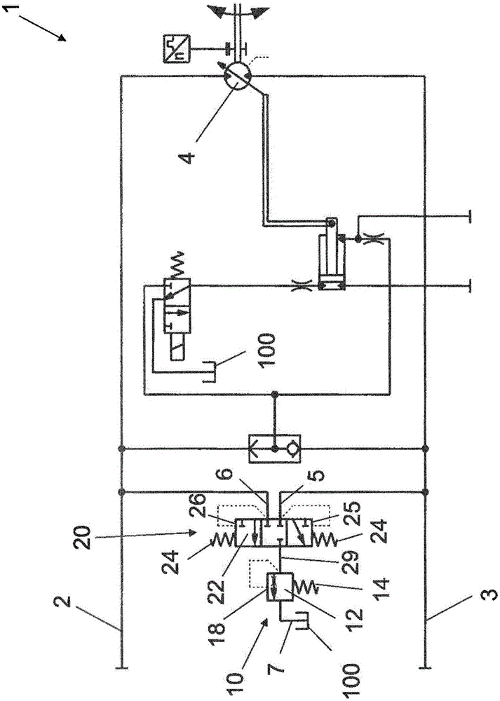
[0035] figure 1 A circuit diagram of a loop flushing system known from the prior art, for example the loop flushing system taught in US 6,430,923 B1, is schematically shown. In this system, each working line 2 and 3 of the hydrostatic propulsion system is led to one of the sensing diameters 25 or 26 of the shuttle valve spool 22 of the shuttle valve 20 . If the pressure difference between the high pressure side and the low pressure side produces a pressure on one of the sensing diameters 25 or 26 that is higher than the force of the shuttle valve spring 24 arranged on the opposite sensing diameter 26 or 25, the shuttle valve The spool 22 is moved so that the fluid connection to the passage 29 is opened for one of the inlet ports 5 or 6 (inlet port for low pressure). The fluid pressure generated in passage 29 in this manner is used to generate a cracking pressure against the force of flush valve spring 14 on sensing surface 18 of flush valve cartridge 12 of flush valve 10 . T...


PUM


Abstract

A hydraulic loop-flushing device for a hydrostatic apparatus comprises a valve housing having a cylindrical valve bore. The cylindrical valve bore is provided with a high pressure inlet, a low pressure inlet and a discharge outlet. A first flushing valve spool is arranged elastically pre-stressed within the valve bore for enabling a fluid connection between the low pressure inlet and the discharge outlet by means of a first fluid channel. Further, a shuttle valve spool is arranged elastically pre-stressed within the valve bore for further enabling the fluid connection between the low pressure inlet and the discharge outlet by means of a fluid passageway. For this the first flushing valve spool and the shuttle valve spool are arranged concentrically and moveable relative to each other, and the fluid connection between the low pressure inlet and the discharge outlet is enabled only if both the first flushing valve spool and the shuttle valve spool are in the respective open positions.

Description

technical field [0001] The invention relates to a hydraulic circuit flushing device for hydrostatic equipment according to the body of claim 1 . The invention also relates to hydraulic equipment using such a circuit flushing device. Background technique [0002] Hydraulic fluid for generating hydraulic pressure and hydraulic performance in hydraulic machines having a closed circuit for the hydraulic fluid, such as hydrostatic drive or propulsion systems, especially in hydrostatic machines, such as hydrostatic pumps and hydrostatic motors are subjected to elevated temperatures during operation of the machine or plant, respectively. Additionally, during operation, the movable parts of hydrostatic equipment, such as supports, bearings, guide shoes, etc., require lubrication to function properly and prevent overheating. Such lubrication and protection against overheating is usually performed by a loop flushing system that produces - in addition to the inevitable leakage of val...

Claims


Application Information

Patent Timeline
IPC IPC(8): F15B13/042F16H61/4104F15B21/04F15B21/0423F15B21/045
CPCF15B13/042F16H61/4104F15B7/006F15B13/024F15B2211/20561F15B2211/20569F15B2211/27F15B2211/3052F15B2211/31558F15B2211/50518F15B2211/5159F15B2211/611F15B2211/62F15B21/005F15B21/045F15B21/04F15B21/0423F16H61/4165
Inventor 安·斯特布劳
Owner DANFOSS POWER SOLUTIONS GMBH & CO
Why Eureka
Try Eureka