Low temperature protector and working method thereof

A protector, low temperature technology, applied in the valve operation/release device, valve details, multi-way valve and other directions, can solve the problems of economic loss, freezing cracked water pipe water purification products, damage to protective measures, etc., to achieve a simple structure. Effect

Active Publication Date: 2017-02-01
XIAMEN BAILIN WATER PURIFICATION TECH CO LTD
View PDF9 Cites 5 Cited by
  • Summary
  • Abstract
  • Description
  • Claims
  • Application Information

AI Technical Summary

Problems solved by technology

[0002] When the temperature is extremely low in winter, some areas or household pipelines do not take protective measures or the protective measures are damaged and are not found in time. Because the water purification equipment or water use equipment of household pipelines is filled with water, the water freezes and expands, often freezing and cracking water pipes Or water purification products, when the temperature rises, the ice melts, causing the tap water to directly flood the house, causing unnecessary economic losses

Method used


Image

  • Low temperature protector and working method thereof
  • Low temperature protector and working method thereof
  • Low temperature protector and working method thereof

Examples


Embodiment 1

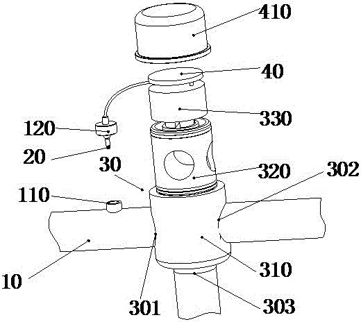
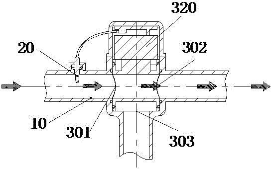
[0025] Embodiment 1: The switching valve includes a housing 310, a central switching pin 320 disposed in the housing 310, and a stepper motor 330 that drives the central switching pin to rotate. The output shaft of the stepping motor 330 is connected to the central switching pin 320 Fixedly connected, the central switching plug 320 has a first water flow channel set corresponding to the water inlet 301 and the water outlet 302, a second water flow channel set corresponding to the water outlet 302 and the water outlet 303, the stepper motor 330 and the control module 40 electrical connection.

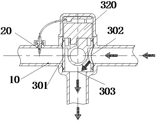
[0026] In this embodiment, when the temperature is lower than the set value of the temperature sensor 20, the temperature sensor 20 controls the stepper motor 330 through the control device to drive the center switching pin 320 to rotate so as to deflect the first water flow channel facing the water inlet 301 and the water outlet 302. The disconnection is realized, and the central switch...

Embodiment 2

[0029] Embodiment 2: The switching valve described in this embodiment includes a housing 310, a central switching pin 320 arranged in the housing 310, and a driving device for driving the central switching pin to move up and down. The driving device includes a motor 330 and the output of the motor 330 Control the rotation of the gear 331. The center switch pin 320 is fixed with a rack 321 matching the gear. When the motor 330 rotates, the drive gear 331 drives the rack 321 to move the center switch pin 320 up and down.

[0030] The water inlet 301, the water outlet 302 for outputting the water source, and the outlet 303 used to realize the drainage in the switching device are arranged longitudinally from high position to low position, and the central switching plug 320 has a plug 322 to block the water inlet 301 or the drainage port 303 .

[0031] When working, when the temperature is lower than the set value of the temperature sensor 20, the temperature sensor 20 controls the...

Embodiment 3

[0034] Embodiment 3. In this embodiment, the switching valve is a solenoid valve independently arranged at the water inlet and the drain, and the solenoid valve is electrically connected to the control module. The control device controls the operation of the two switching valves respectively. When the temperature is low, the solenoid valve at the water inlet is closed, and the solenoid valve at the drain port is opened to realize drainage; when the temperature is high, the solenoid valve at the water inlet is opened, and the solenoid valve at the drain port is closed to realize normal water supply. .

[0035] In the above embodiment, the water inlet pipeline 10 is provided with a detector branch pipe 110, and the detector branch pipe is threaded with a nut 120, and the temperature sensor 20 extends into the tap water inlet pipe through the nut 120.

[0036] In practical applications, the waterway switching device can also be provided with a filter device or directly replaced w...


PUM


Abstract

The invention provides a low temperature protector and a working method thereof. The low temperature protector comprises a water inlet pipeline for providing a water source for a water-requiring device. A temperature sensor and a water path switching device for achieving switching of the water source are arranged between the water inlet pipeline and the water-requiring device. The water path switching device comprises a water inlet communicating with the water inlet pipeline, a water outlet for discharging the water source, and a drainage opening for achieving drainage in the switching device. A switching valve is arranged in the water path switching device, the temperature sensor is connected with the switching valve through a control module, and when the temperature is lower than a preset value, water current switching is achieved, and water is prevented from being supplied to the water-requiring device. The low temperature protector is simple in structure, the temperature sensor is utilized for feeding back the water temperature so that water feeding can be started or stopped, and the situations that at the extremely low temperature in winter, water in a water pipe or a water purification product or the water-requiring device is frozen, consequently, frost cracking of the water pipe or the water purification product is caused, and unnecessary economic losses are caused are avoided.

Description

technical field [0001] The invention relates to a low temperature protector and its working method. Background technique [0002] When the temperature is extremely low in winter, some areas or household pipelines do not take protective measures or the protective measures are damaged and are not found in time. Because the water purification equipment or water use equipment of household pipelines is filled with water, the water freezes and expands, often freezing and cracking water pipes Or water purification products, when the temperature rises, the ice melts, causing the tap water to directly flood the house, causing unnecessary economic losses. Contents of the invention [0003] The present invention improves the above-mentioned problems, that is, the technical problem to be solved by the present invention is that the household pipelines in winter are prone to water freezing and cracking of water pipes or water purification products causing economic losses if no protectiv...

Claims


Application Information

Patent Timeline
IPC IPC(8): F16K31/66F16K31/04F16K31/54F16K11/085F16K11/044F16K11/10
CPCF16K11/044F16K11/085F16K11/10F16K31/002F16K31/02F16K31/047F16K31/54F16K37/0091
Inventor 许鸿锟詹丰顺
Owner XIAMEN BAILIN WATER PURIFICATION TECH CO LTD
Why Eureka
Try Eureka