A U-shaped microchannel dehumidification heat pipe and its application method

A micro-channel, dehumidification heat technology, applied in the field of heat pipes, can solve the problems of inflexible overall size design of dehumidification heat pipes, high production and maintenance costs, inconvenient installation and use, etc., and achieves flexible and convenient design, simple structure, and high degree of automation. Effect

Active Publication Date: 2022-02-18
内蒙古创达热管节能设备有限公司
View PDF11 Cites 0 Cited by
  • Summary
  • Abstract
  • Description
  • Claims
  • Application Information

AI Technical Summary

Problems solved by technology

However, the current dehumidification devices and heat pipes exist: relatively complicated structural design, less combination of the two applications, single function, high production and maintenance costs, high degree of automation, inflexible design of the overall size of the dehumidification heat pipe, and inconvenient installation and use, etc. and other defects

Method used


Image

  • A U-shaped microchannel dehumidification heat pipe and its application method

Examples


Embodiment Construction

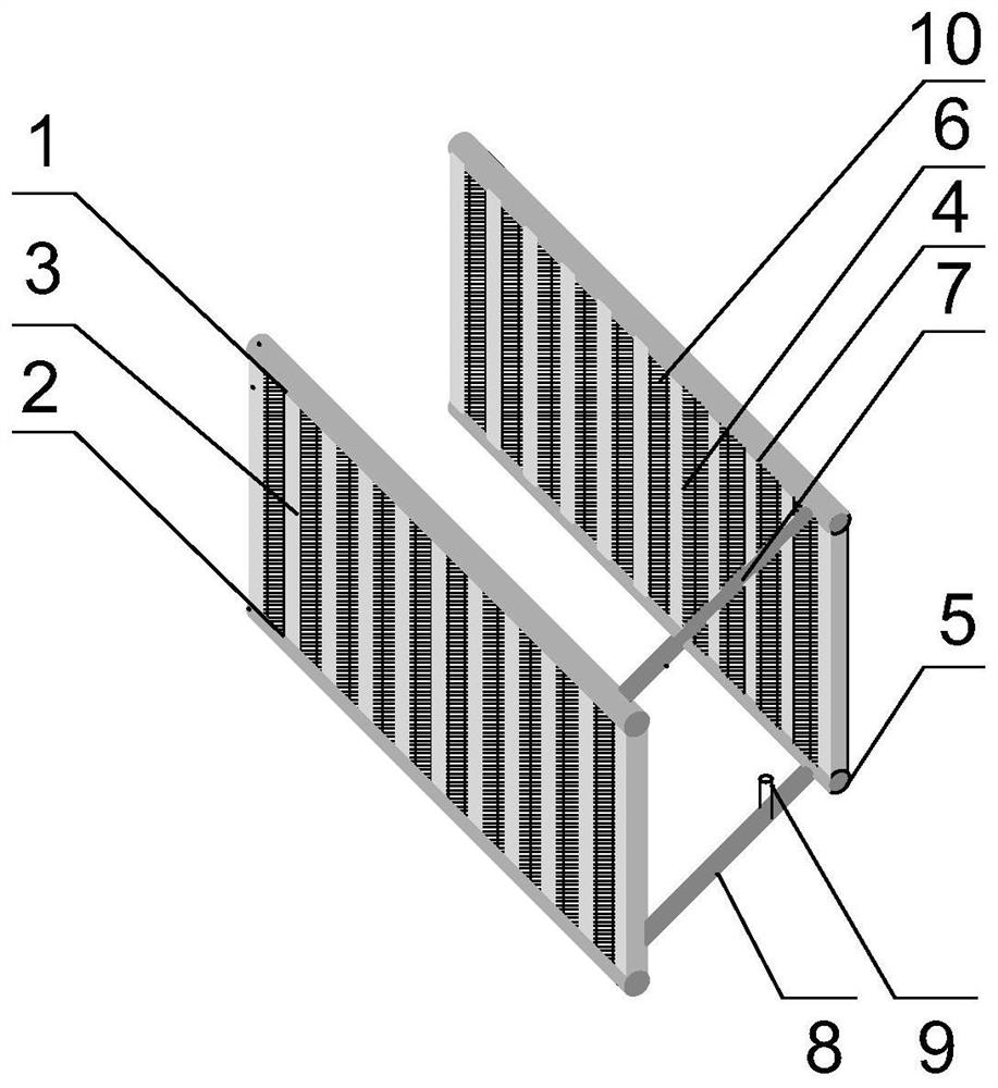
[0020] Attached below figure 1 A U-shaped microchannel dehumidification heat pipe of the present invention and its application method are described in detail.

[0021] A U-shaped microchannel dehumidification heat pipe, the U-shaped microchannel dehumidification heat pipe includes a first part arranged on the front side of the surface cooler, a second part arranged on the rear side of the surface cooler, and connecting the first part and the second part The third part; wherein, the first part includes the first gas pipe 1 and the refrigerant liquid inlet pipe 2, and also includes the first microchannel branch pipe 3 communicated with the first gas pipe and the refrigerant liquid inlet pipe respectively; The second part includes the second gas pipe 4 and the refrigerant liquid return pipe 5, and also includes the second microchannel branch pipe 6 communicated with the second gas pipe and the refrigerant liquid return pipe; the third part includes the first gas pipe and the refr...


PUM


Abstract

The invention relates to a U-shaped micro-channel dehumidification heat pipe and a method of using the same, comprising a first part arranged on the front side of the surface cooler, a second part arranged on the rear side of the surface cooler, and a connection between the first part and the second part. The third part; the first part includes a first gas pipe and a refrigerant liquid inlet pipe, and also includes a first microchannel branch pipe which is respectively communicated with the first gas pipe and the refrigerant liquid inlet pipe; the second part includes a second gas pipe and the refrigerant liquid return pipe, and also includes a second microchannel branch pipe that is respectively communicated with the second gas pipe and the refrigerant liquid return pipe; the third component includes a gas connection pipe that is communicated with the first gas pipe and the second gas pipe respectively. , and also includes a liquid connecting pipe respectively connected with the refrigerant liquid inlet pipe and the refrigerant liquid return pipe. The utility model has the advantages of simple structure, reasonable design, high degree of automation, high heat exchange efficiency, reliable and stable operation performance, and can realize gravity return of refrigeration working medium by means of height difference, reducing energy loss, and can be widely popularized and applied.

Description

technical field [0001] The invention relates to the technical field of heat pipes, in particular to a U-shaped microchannel dehumidification heat pipe and a use method thereof. Background technique [0002] With the continuous improvement of people's living standards, dehumidifiers and heat pipes are increasingly widely used by people. However, the current dehumidification devices and heat pipes exist: relatively complicated structural design, less combination of the two applications, single function, high production and maintenance costs, high degree of automation, inflexible design of the overall size of the dehumidification heat pipe, and inconvenient installation and use, etc. and other defects. Therefore, it is of great research significance to propose a dehumidification heat pipe with a simple structure and a reasonable design that can overcome the above-mentioned shortcomings. Contents of the invention [0003] In view of the above-mentioned deficiencies in the de...

Claims


Application Information

Patent Timeline
Patent Type & Authority Patents(China)
IPC IPC(8): F24F3/14F24F13/30F24F11/89F24F11/64F24F11/85F24F11/58F24F11/52
CPCF24F3/1405F24F11/30F24F11/62F24F13/30F24F2110/00F24F2110/40F24F2140/20F24F11/58
Inventor 江鑫
Owner 内蒙古创达热管节能设备有限公司
Why Eureka
Try Eureka