Air conditioner windshield driving device

A driving device and wind baffle technology, applied in space heating and ventilation details, heating methods, lighting and heating equipment, etc., can solve the problems of difficult adjustment of motion trajectory, high production cost, and high design difficulty, and achieve opening and closing The effect of easy angle, simple structure and reduced design cost

Active Publication Date: 2021-11-30
GREE ELECTRIC APPLIANCES INC
View PDF12 Cites 0 Cited by
  • Summary
  • Abstract
  • Description
  • Claims
  • Application Information

AI Technical Summary

Problems solved by technology

[0003] Therefore, the technical problem to be solved by the present invention is to overcome the technical defects of the air conditioner windshield driving device in the prior art, such as high production cost, high design difficulty, and difficult adjustment of motion trajectory, thereby providing a low-cost production , an air conditioner windshield driving device with low design difficulty and easy adjustment of motion trajectory

Method used


Image

  • Air conditioner windshield driving device
  • Air conditioner windshield driving device

Examples


Embodiment 1

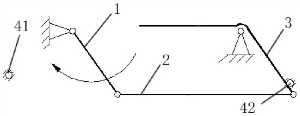
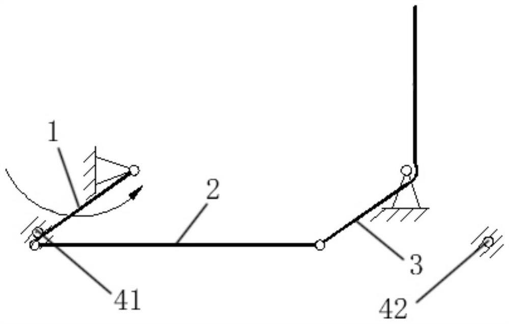
[0029] refer to figure 1 and figure 2 , the present embodiment provides a driving device for the wind baffle of an air conditioner, the driving device includes a driving motor, fixedly installed on a fixed frame, and has a drive shaft with a fixed position relative to the fixed frame; the baffle shaft is wound around the The tuyere rotates relative to the fixed axis of the fixed frame, the baffle shaft is parallel to the drive shaft; and a transmission device is arranged between the drive shaft and the baffle shaft to move the The rotational torque of the drive shaft is transmitted to the flap shaft. Wherein, the transmission device includes a first connecting rod 1 whose one end is fixedly connected with the drive shaft, a second connecting rod 2 whose one end is fixedly connected with the wind baffle and the baffle shaft, and the two ends are respectively hinged to the first connecting rod through the first hinge point. The connecting rod 2 and the third connecting rod 2 ...

Embodiment approach

[0033] An alternative embodiment is to change the positions of the first limiter 41 and the second limiter 42, so as to realize the function of adjusting the unfolded and closed positions of the windshield, for example, to move the position of the first limiter 42 toward figure 1 Move the middle left side horizontally to increase the deployment angle of the wind deflector. Similar alternative implementation manners will not be described in detail.

[0034] Another alternative embodiment is to shorten the length of the second connecting rod 3 without changing the position of the baffle axis, while extending the length of the third connecting rod 2 to increase the rotation rate of the wind baffle. Similar alternative implementation manners will not be described in detail.

[0035] It should be noted that, when driving a wind baffle, one wind baffle driving device of an air conditioner described in the above-mentioned embodiment may be used, or multiple same wind baffle driving de...


PUM


Abstract

The invention discloses an air baffle driving device for an air conditioner, which comprises: a driving motor fixedly installed on a fixed frame and having a drive shaft with a fixed position relative to the fixed frame; The fixed axis rotates, and the baffle shaft is parallel to the drive shaft; the transmission device is arranged between the drive shaft and the baffle shaft, and is used to transmit the rotational torque of the drive shaft to the baffle shaft; the transmission device has one end connected to the drive shaft The first connecting rod fixedly connected; the second connecting rod fixedly connected to the windshield and the baffle shaft at one end, and the two ends are respectively hinged to the first connecting rod through the first hinge point and hinged to the second connecting rod through the second hinge point the third link. The gear transmission mechanism is replaced by the planar four-bar linkage mechanism. Since the transmission design of the planar four-bar linkage mechanism is easier, the design of the gear can be saved by the designer, and the design cost is reduced; and the structure of the planar four-bar linkage mechanism is simpler. Compared with the gear transmission mechanism, the production cost is reduced.

Description

technical field [0001] The invention relates to the technical field of heating / refrigerating equipment, in particular to an air conditioner wind baffle driving device. Background technique [0002] In the past, the air inlet of the wall-mounted air conditioner was exposed outside the housing of the indoor unit of the air conditioner, and the exposed air inlet easily accumulated dust, which affected the appearance of the air conditioner. Those skilled in the art have installed a wind baffle at the air inlet of the housing of the indoor unit of the wall-mounted air conditioner. By driving the wind baffle to rotate, the air inlet can be opened or closed. In order to avoid the technical defect of dust accumulation at the air inlet; at the same time, the effective air inlet area of ​​the air inlet can be adjusted according to the rotation angle of the wind baffle, so as to adjust the size of the air inlet. The transmission mechanism currently used to drive movable baffles such a...

Claims


Application Information

Patent Timeline
Patent Type & Authority Patents(China)
IPC IPC(8): F24F13/14
CPCF24F13/1426F24F2013/1433F24F2013/1446
Inventor 李开华孟智宁强延黄煜鹏何娜刘慧周文伟谢承琪成凯杨义红
Owner GREE ELECTRIC APPLIANCES INC
Why Eureka
Try Eureka