
Fertilizer drying device

A technology for drying equipment and fertilizers, which is applied in drying, dryer, manure drying and other directions, can solve the problems that the drying wind is not easy to control, the air inlet is single, and the quality of fertilizers is affected, so as to improve the processing quality and product qualification. rate, increase drying area and time, and the effect of compound fertilizer particle uniformity

Inactive Publication Date: 2017-02-01
天津亚泰昊德科技有限公司
View PDF6 Cites 3 Cited by
  • Summary
  • Abstract
  • Description
  • Claims
  • Application Information

AI Technical Summary

Problems solved by technology

In the existing compound fertilizer production process, drying is a necessary step, and the dried fertilizer can be processed later. Drying can determine the quality of the fertilizer, but the disadvantage of the existing dryer is that the drying The wind power is not easy to control the wind power, and the air inlet is single, so the surface fertilizer within the wind power coverage area is easy to be dried quickly, while the fertilizer covered below is not dried thoroughly, making the fertilizer quality uneven, and during the drying process, Due to the short contact time between chemical fertilizers and hot air, it will cause incomplete drying of chemical fertilizers and affect the quality of chemical fertilizers

Method used


Image

  • Fertilizer drying device

Examples


Embodiment Construction

[0018] It should be noted that, in the case of no conflict, the embodiments of the present invention and the features in the embodiments can be combined with each other.

[0019] In describing the present invention, it should be understood that the terms "center", "longitudinal", "transverse", "upper", "lower", "front", "rear", "left", "right", " The orientations or positional relationships indicated by "vertical", "horizontal", "top", "bottom", "inner" and "outer" are based on the orientations or positional relationships shown in the drawings, and are only for the convenience of describing the present invention and Simplified descriptions, rather than indicating or implying that the device or element referred to must have a particular orientation, be constructed and operate in a particular orientation, and thus should not be construed as limiting the invention. In addition, the terms "first", "second", etc. are used for descriptive purposes only, and should not be understood ...


PUM


Abstract

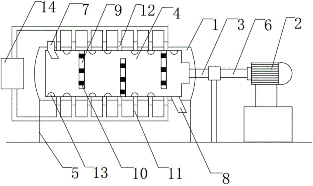
The invention provides a fertilizer drying device comprising a drying roller, a drive motor and a rotating shaft. A drying lining is arranged in the drying roller. The drying lining is connected with an output shaft of the drive motor through the rotating shaft. A wet fertilizer inlet is formed in the upper side of one end of the drying lining. A dry fertilizer outlet is formed in the lower side of the other end of the drying lining. The upper inner wall and the lower inner wall of the drying lining are provided with partition plates which are arranged at equal intervals in a staggered mode. Each partition plate is provided with electric heaters. The inner surface of the drying lining is provided with semicircular protrusions. The upper surface and the lower surface of the drying lining are provided with a plurality of exhaust pipes. An air outlet of each exhaust pipe is provided with a filter screen. After compound fertilizer enters the drying lining, wind force can be applied to the compound fertilizer from the upper side and the lower side, and the wind force dead corner condition is effectively avoided. Meanwhile, the filter screens at the air outlets effectively prevent the compound fertilizer from being mixed with impurities in the drying process. The drying roller can conduct air drying and electric heating drying on the materials inside the drying roller synchronously, and therefore the processing quality and the yield of the product are greatly improved.

Description

technical field [0001] The invention belongs to the technical field of chemical fertilizer production equipment, in particular to chemical fertilizer drying equipment. Background technique [0002] Chemical fertilizers are important compounds that help plants grow and are essential in agricultural production. Compound fertilizers refer to the three nutrients nitrogen, phosphorus and potassium. Compound fertilizers refer to at least two of the three nutrients nitrogen, phosphorus and potassium. It is a fertilizer made only by chemical methods with the indicated amount of nutrients. The compound fertilizer has the advantages of high nutrient content, less auxiliary components and good physical properties. In the existing compound fertilizer production process, drying is a necessary step, and the dried fertilizer can be processed later. Drying can determine the quality of the fertilizer, but the disadvantage of the existing dryer is that the drying The wind power is not easy t...

Claims


Application Information

Patent Timeline
IPC IPC(8): F26B11/06F26B21/00F26B23/04
CPCF26B11/0486F26B21/003F26B23/04F26B2200/12
Inventor 赵东亮云霄
Owner 天津亚泰昊德科技有限公司
Learn More