Shafting centering calculation method of novel shafting structure under specific centering requirement

A calculation method and a technology of structural shafts, applied in the field of steam turbines, can solve problems such as the lack of a new structural shafting calculation method, and achieve the effect of a wide range of engineering application prospects

Inactive Publication Date: 2017-02-01
XI AN JIAOTONG UNIV
View PDF4 Cites 3 Cited by
  • Summary
  • Abstract
  • Description
  • Claims
  • Application Information

AI Technical Summary

Problems solved by technology

When introducing foreign technology, due to technology monopoly, the foreign manufacturer did not provide a calculation method for the centering of the new structural shafting

Method used


Image

  • Shafting centering calculation method of novel shafting structure under specific centering requirement
  • Shafting centering calculation method of novel shafting structure under specific centering requirement
  • Shafting centering calculation method of novel shafting structure under specific centering requirement

Examples


Embodiment Construction

[0033] The present invention will be described in further detail below in conjunction with the accompanying drawings.

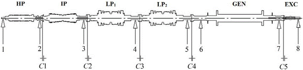
[0034] figure 1 It is a schematic diagram of a typical structure of a shaft system of a single support structure.

[0035] see Figure 2 to Figure 9 , the present invention is a calculation method for shafting centering of a new type of shafting structure under specific alignment requirements, comprising the following steps:

[0036] 1) Determination of the mechanical boundary conditions of the shaft system of the single support structure.

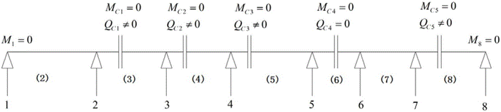
[0037] Since the shafting installation needs to ensure that the bending moment at each coupling is zero, so under the condition that the bending moment of the coupling is zero, the stress on each bearing and each coupling of the shafting is as follows figure 2 shown. Since the medium-pressure rotor, low-pressure rotor and exciter rotor are all single-support structures, there are shear forces at couplings C1, C2, C3 ...


PUM


Abstract

The invention discloses a shafting centering calculation method of a novel shafting structure under a specific centering requirement. The method is used for guiding selection of each bearing elevation and on-site mounting of large machine set shafting. The method is combined with a transfer matrix method, a moment balance equation which reflects the relation among a shafting structure, a bearing bending moment and the elevation is provided on the basis of a three-bending-moment equation, and a shafting centering calculation model is established. According to the centering requirement during mounting of single-supporting structure shafting, a calculation method for solving each bearing elevation of the single-supporting structure shafting under the condition that the bending moment of a shaft coupler is zero is provided. The bearing elevation of the single-supporting structure shafting is calculated by adopting the method, and the correctness of the shafting centering calculation method is verified by comparing the bearing elevation with the bearing elevation actually measured by a manufacturer. The method can provide guidance for on-side mounting of the large machine set and selection of the bearing elevation.

Description

Technical field: [0001] The invention relates to the technical field of steam turbines, in particular to a shaft alignment calculation method for a novel shaft architecture under specific alignment requirements. Background technique: [0002] In the actual operation of the steam turbine generator set, it is necessary to ensure that the shafting formed by the connection of the rotors is a smooth and continuous curve. About 60% of the vibration faults of the rotating machinery are caused by the misalignment of the shafting. If the turbo-generator set with misalignment faults runs for a long time, problems such as dynamic and static friction, uneven bearing load and increased air leakage loss will occur. With the continuous increase of unit capacity, the shafting structure has become compact and complex. The new single-support structure shafting is widely used in the design of the unit, and the bending moment at the coupling is an important reason for inducing shafting vibratio...

Claims


Application Information

Patent Timeline
Patent Type & Authority Applications(China)
IPC IPC(8): G06F17/50
CPCG06F30/17
Inventor 袁奇刘洋陈谦
Owner XI AN JIAOTONG UNIV
Why Eureka
Try Eureka