
Pressurized-water nuclear reactor structure

A nuclear reactor, pressurized water type technology, applied in nuclear reactors, nuclear reactor monitoring, reactors, etc., can solve the problems of increasing the number of measuring tube sockets, unreasonable design, unreasonable flow distribution of the lower head, etc.

Inactive Publication Date: 2017-02-01
NUCLEAR POWER INSTITUTE OF CHINA
View PDF9 Cites 8 Cited by
  • Summary
  • Abstract
  • Description
  • Claims
  • Application Information

AI Technical Summary

Problems solved by technology

[0006] The invention provides a pressurized water type nuclear reactor structure, which solves the unreasonable design of the existing pressurized water type nuclear reactor structure. When the in-core measurement guide structure in the upper head and the penetrating piece on the top of the pressure vessel are led out of the reactor, the number of measurement tube sockets in the reactor on the top cover is greatly increased, and the flow distribution of the lower head is unreasonable, and the cooling effect of the reactor pressure vessel is poor. Due to poor technical problems, it can accommodate and support 177 sets of fuel assemblies, achieve a 60-year life of the reactor, and realize that the neutron flux measurement detectors, temperature measurement detectors and water level measurement detectors are located in the upper head of the pressure vessel. The in-core measurement guide structure and the pressure vessel top penetrating piece lead to the reactor; it can meet the requirements of water level measurement; on the premise of realizing the functions of the reactor internals, the coolant flow into the core can be reasonably distributed; in addition, the reactor top structure can be It meets the functional requirements of the reactor top and meets the requirements for the operating space after the neutron flux measuring detector, temperature measuring detector and water level measuring detector are led out from the top; the thermal insulation layer can also realize the technical effect of rapid cooling outside the reactor pressure vessel

Method used


Image

  • Pressurized-water nuclear reactor structure
  • Pressurized-water nuclear reactor structure
  • Pressurized-water nuclear reactor structure

Examples


Embodiment 1

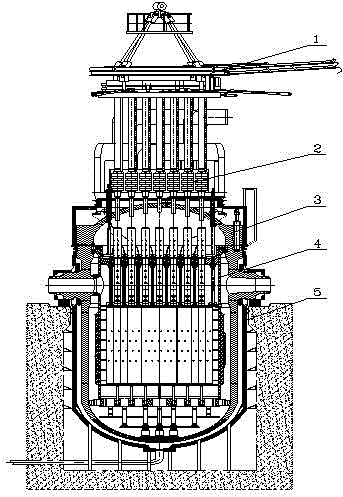
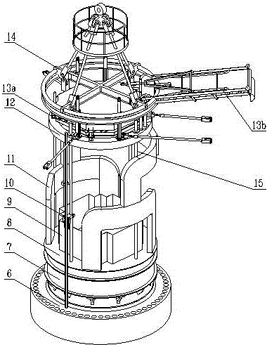
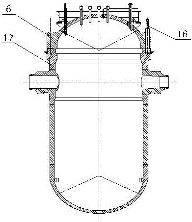
[0028] In embodiment one, a pressurized water nuclear reactor structure is provided, please refer to Figure 1-Figure 7 , the structure includes:

[0029] Distributed stack top 1, drive mechanism 2, pressure vessel 3, stack internal components 4, heat preservation components 5, the decentralized stack top is connected to the pressure vessel top cover 6, and the heat preservation components are arranged outside the pressure vessel On the surface, the internal components of the pile are hung on the support steps of the pressure vessel, and the driving mechanism is installed on the top cover of the pressure vessel, wherein the decentralized pile top specifically includes: the ventilation hood support 7, the lower wind hood assembly 8. Cooling coaming 9, guide rail 10, air duct assembly 11, anti-seismic support device 12, cable bracket 13a, cable bridge assembly 13b, top cover hanger upper structure 14, lower boom 15, wherein the ventilation hood supports and The top cover of the...


PUM


Abstract

The invention discloses a pressurized-water nuclear reactor structure. The structure comprises a distributed reactor top, a driving mechanism, a pressure container, an in-reactor member and a heat preservation member. The distributed reactor top is connected with a top cover of the pressure container, the heat preservation member is arranged on the outer surface of the pressure container, the in-reactor member is hung on a supporting step of the pressure container, and the driving mechanism is installed on the top cover of the pressure container. It is achieved that a neutron flux measuring detector, a temperature measuring detector and a water-level measuring detector are guided out of a reactor through an in-reactor measuring guiding structure located in an upper end socket of the pressure container and a penetration piece at the top of the pressure container, and it is avoided that the number of in-reactor measuring pipe bases on the top cover is increased; the water level measuring requirements can be met; the quantity of a coolant entering a reactor core is reasonably distributed; due to the heat preservation layer, the advantage that the external of the pressure container of the reactor can be rapidly cooled can also be achieved.

Description

technical field [0001] The invention relates to the research field of pressurized water nuclear reactors, in particular to a pressurized water nuclear reactor structure. Background technique [0002] The ACP1000 pressurized water reactor is the third-generation pressurized water reactor independently designed by China. The ACP1000 pressurized water reactor uses 177 sets of fuel assemblies to form the core, which will withstand an earthquake acceleration of 0.3g and extend the reactor life to 60 years. [0003] Compared with the second-generation and second-generation improved pressurized water reactors, the third-generation pressurized water reactors cancel the neutron measurement instrument bushing and neutron measurement tube socket located at the bottom head of the reactor pressure vessel, and the neutron flux measurement detector, The temperature measurement probe and the water level measurement probe are led out of the reactor through the in-stack measurement guide stru...

Claims


Application Information

Patent Timeline
IPC IPC(8): G21C1/08G21C3/33G21C13/02G21C15/12G21C17/035
CPCG21C1/086G21C3/33G21C13/02G21C15/12G21C17/035Y02E30/30
Inventor 李燕夏欣余志伟李娜何培峰邱天王庆田李宁杨博周高斌张翼唐向东舒翔穆伟蒋兴钧
Owner NUCLEAR POWER INSTITUTE OF CHINA
Learn More