
Initial position identification method of rotor of permanent magnet synchronous motor

A technology of rotor initial position and permanent magnet synchronous motor, which is applied in the control of generator, motor generator control, AC motor control, etc., and can solve the problems of poor engineering practicability and low reliability

Active Publication Date: 2017-02-01
HEFEI UNIV OF TECH
View PDF5 Cites 17 Cited by
  • Summary
  • Abstract
  • Description
  • Claims
  • Application Information

AI Technical Summary

Problems solved by technology

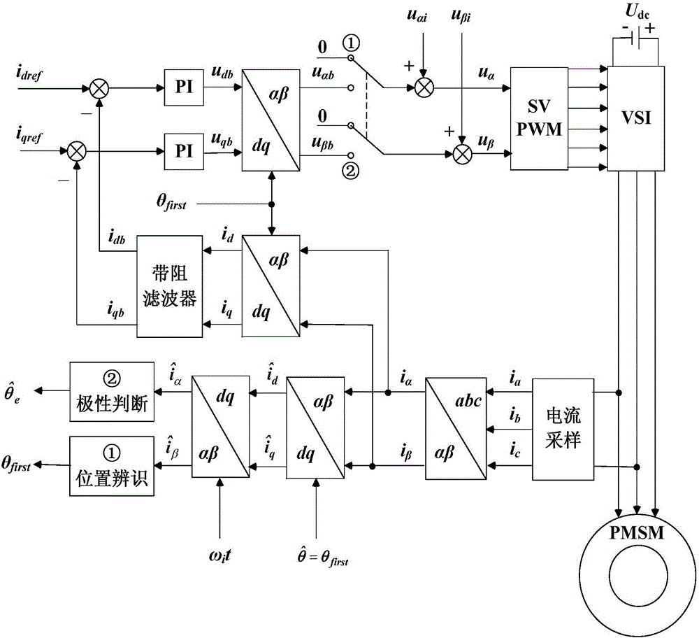
[0010] The technical problem to be solved by the present invention is to provide a permanent magnet synchronous motor rotor initial position identification method for the problems of rotor rotation, poor engineering practicability and low reliability in the existing permanent magnet synchronous motor rotor initial position identification. The high-frequency voltage signal is injected into the motor winding, and the three-phase current i is obtained by sampling a i b and i c , and then get the target current through coordinate transformation Used to calculate the initial value of the rotor position θ first , It is used to judge the polarity, and output the initial position identification value of the rotor after polarity compensation

Method used


Image

  • Initial position identification method of rotor of permanent magnet synchronous motor
  • Initial position identification method of rotor of permanent magnet synchronous motor
  • Initial position identification method of rotor of permanent magnet synchronous motor

Examples


Embodiment Construction

[0053] The specific implementation manners of the present invention will be described below in conjunction with the accompanying drawings.

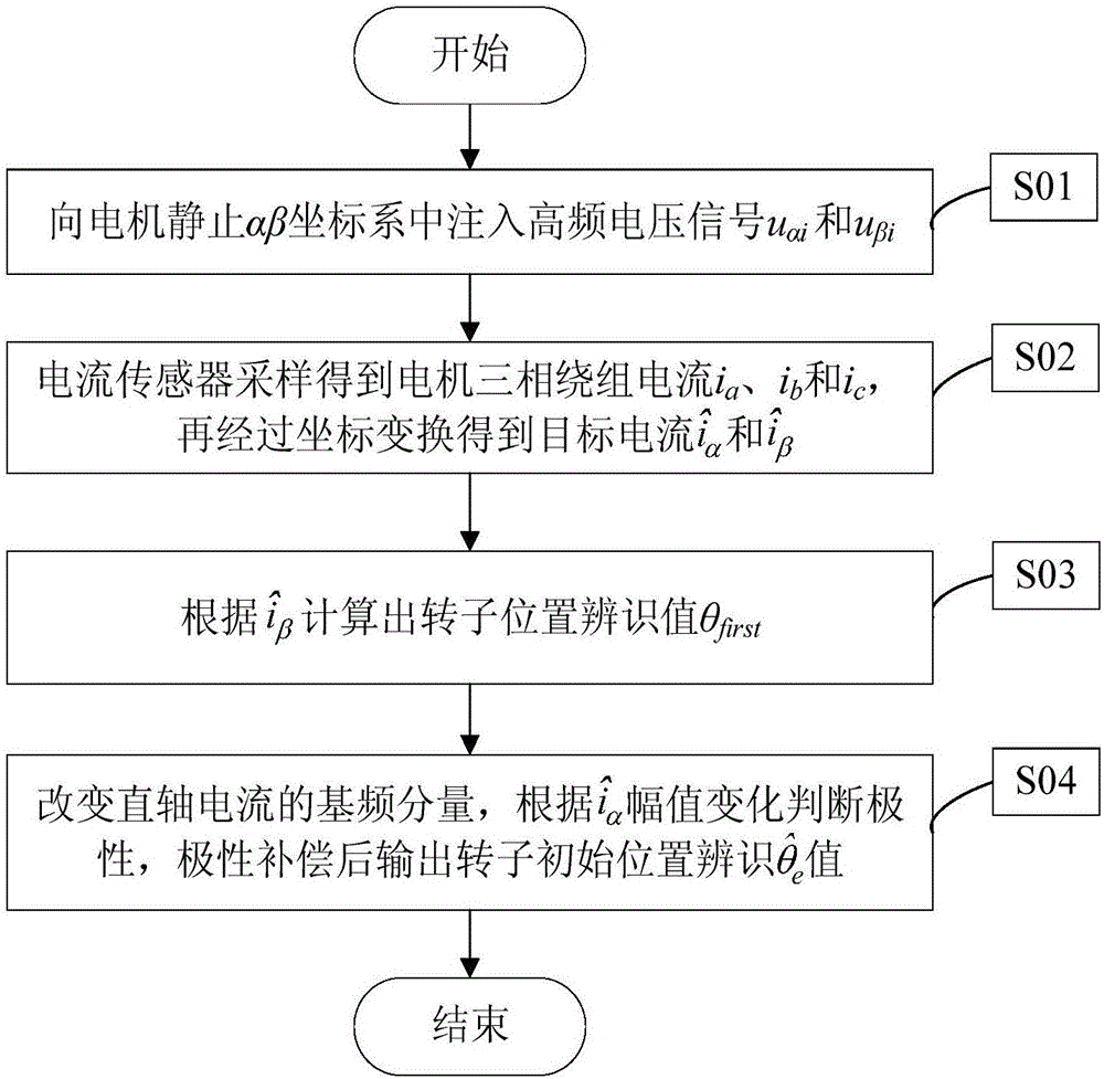
[0054] figure 1 It is a flow chart of the method of the present invention, comprising the following steps:

[0055] Step S01, inject high-frequency voltage signal u into the static αβ coordinate system of the motor αi , u βi ;

[0056] Step S02, the current sensor samples and obtains the motor three-phase winding current i a i b and i c , and then get the target current through coordinate transformation and Coordinate Transform Angle to Estimated Angle

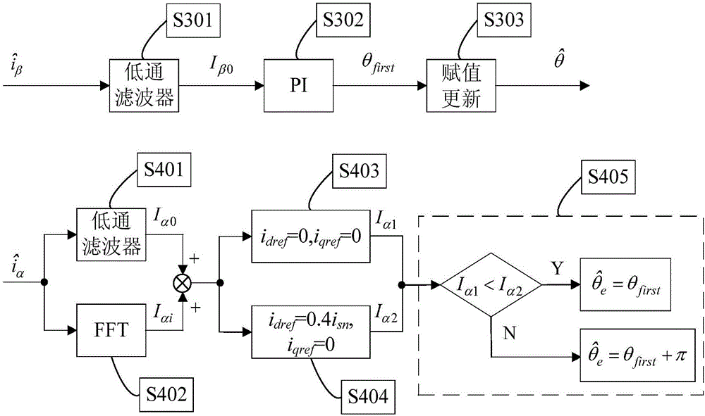
[0057] Step S03, obtained according to step S02 Calculate the rotor position initial value θ first , its implementation flow chart is as follows figure 2 shown, including the following steps:

[0058] Step S301, using a low-pass filter pair Perform filtering to obtain the DC flow I β0 ,

[0059] Step S302, the I β0 As the input of the PI regulator, adjust the PI par...


PUM


Abstract

The invention discloses an initial position identification method of a rotor of a permanent magnet synchronous motor, belongs to the field of motor control, and aims at solving the problems of rotor rotation, poor engineering applicability and low reliability in an existing initial position identification method. The method comprises the steps of injecting a high-frequency voltage signal into a motor winding, obtaining three-phase current ia, ib and ic by sampling, obtaining target current as shown in the specification through coordinate transformation for calculating an initial identification value thetafirst of the rotor position, wherein the target current as shown in the specification is used for judging the polarity; and outputting an initial position identification value, as shown in the specification, of the rotor after polarity compensation. According to the method, the motor is kept in a static state in the implantation process; only a low-pass filter is adopted for obtaining the initial identification value of the position, so that the identification accuracy is effectively improved; the magnetic saturation characteristic is changed through closed-loop adjustment of direct-axis current; and the polarity judgment reliability is strengthened.

Description

technical field [0001] The invention relates to a method for identifying the initial position of a rotor of a permanent magnet synchronous motor, belonging to the field of motor control. Background technique [0002] Permanent magnet synchronous motors have the advantages of high power density, high efficiency and excellent operating performance, and are widely used in electric vehicles, wind power and servo fields. In order to realize the high-precision and high-performance vector control of the motor drive system, the position information of the rotor must be obtained accurately, and the position is usually detected by a mechanical position sensor or a sensorless algorithm. However, no matter which method is used, it is necessary to identify the initial position of the rotor. An inaccurate initial position will lead to a decrease in the load capacity of the motor, or even reverse rotation. Therefore, identification of the initial position of the permanent magnet synchrono...

Claims


Application Information

Patent Timeline
Patent Type & Authority Applications(China)
IPC IPC(8): H02P21/18H02P25/022
Inventor 张兴李浩源杨淑英曹朋朋杨健
Owner HEFEI UNIV OF TECH
Learn More