drying system

A drying system and post-drying technology, applied in the field of drying systems, can solve the problems of longer drying time, slow heating speed, low energy efficiency, etc., and achieve the effect of shortening the drying time

Active Publication Date: 2019-09-20
ZHEJIANG SANHUA INTELLIGENT CONTROLS CO LTD
View PDF4 Cites 0 Cited by
  • Summary
  • Abstract
  • Description
  • Claims
  • Application Information

AI Technical Summary

Problems solved by technology

The temperature rise rate of the above heat pump system is relatively slow to avoid damage to the clothes due to high temperature, which may lead to relatively longer drying time and relatively lower energy efficiency.

Method used


Image

  • drying system
  • drying system
  • drying system

Examples


Embodiment 1

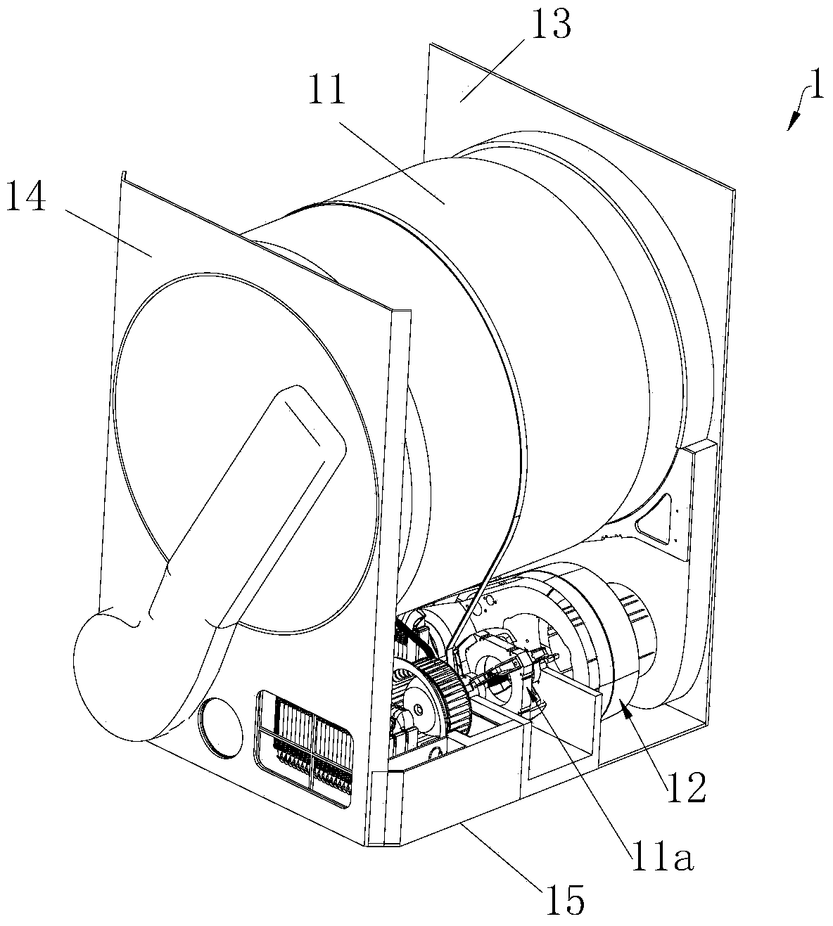
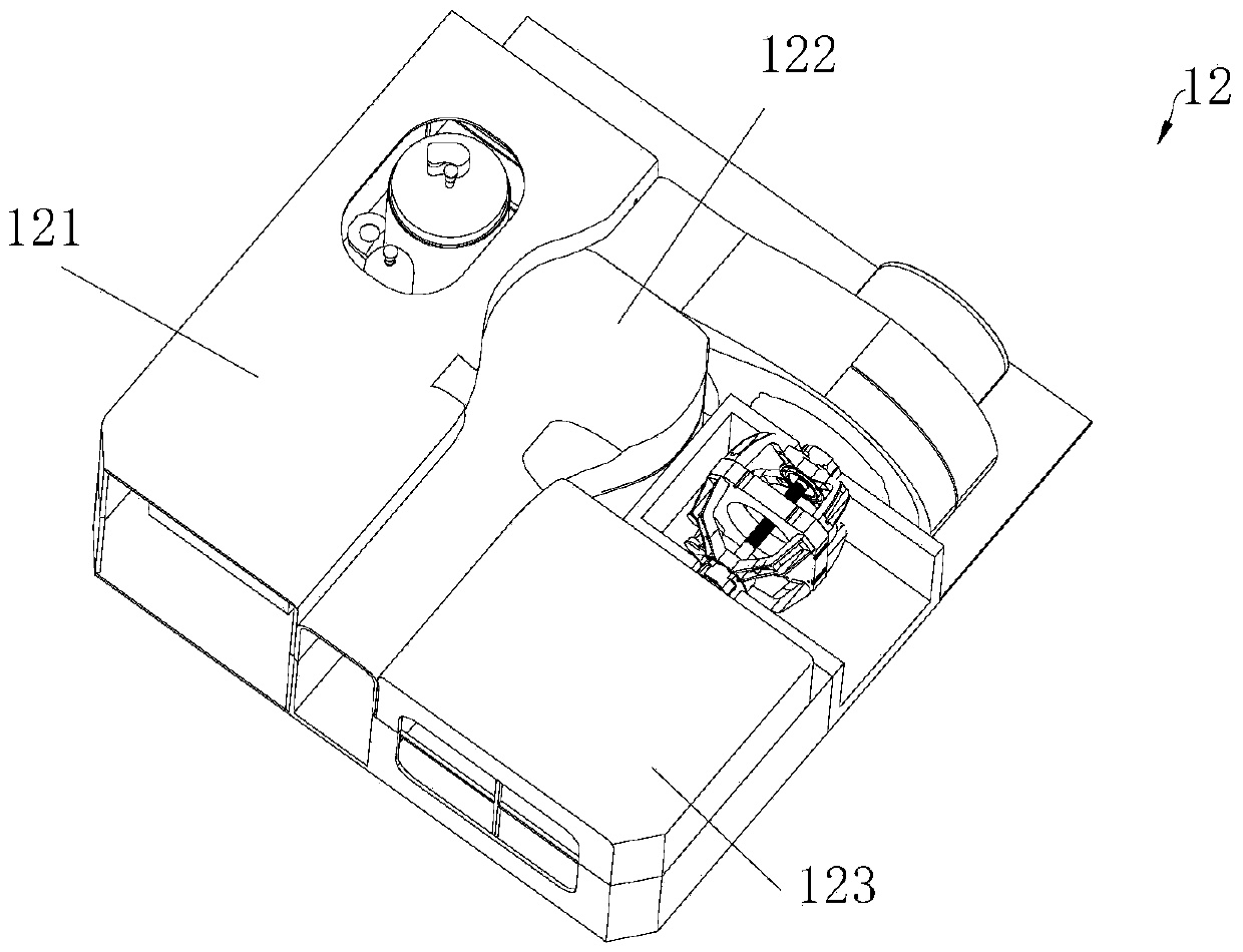
[0035] refer to Figure 1-4 In this embodiment, the drum is used as a drying container as an example for illustration. The clothes dryer 1 includes a cabinet, a drum 11 disposed inside the cabinet, a drying system 12, and a motor 11a for driving the drum 11 to rotate. The body includes a front wall portion 13, a rear wall portion 14 and a bottom 15, the front wall portion 13 is arranged opposite to the rear wall portion 14, the bottom 15 is defined as the space below the drum 11 of the above-mentioned box body, and the drying system 12 Located at the bottom 15 of the box body, the drum 11 is formed with a front side and a rear side correspondingly, the box body is provided with an opening door for opening or closing the front side of the drum 11, and the front side of the drum 11 is assembled and connected with the front wall portion 13 of the box body, The rear side of the drum 11 is assembled and connected with the rear wall portion 14 of the box.

[0036]The drying system ...

Embodiment 2

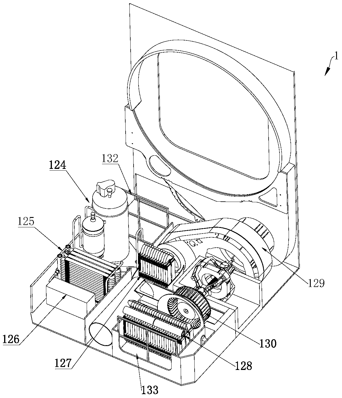
[0046] refer to Figure 6 , 7 , the drying system of this embodiment is substantially the same as the drying system described in Embodiment 1, the only difference lies in the refrigerant circulation system 300'. refer to Figure 7 The heat absorption unit of the refrigerant circulation system 300' in this embodiment includes a heat absorption module 127 and a heat absorption device 128 arranged in parallel. The heat absorption module 127 of the heat absorption unit is used to absorb the heat of the air in the air passage after drying. , the heat absorption device 128 is used to absorb heat from the indoor air environment, wherein the heat absorption device 128 is a first evaporator, and the heat absorption module 127 is a second evaporator. In this embodiment, the drying system further includes a second throttling device 131', a pressure regulating valve 135, and a flow divider 136. The flow divider 136 is arranged on the second heating device 125 and the heat absorption mod...

Embodiment 3

[0050] refer to Figure 8 , 10 , the drying system of this embodiment is substantially the same as the drying system described in Embodiment 1, the difference is that the heat absorbing module 127' of this embodiment includes a heat absorbing part and a heat releasing part, and the heat absorbing part and the heat releasing part The heat transfer between parts can be realized; the heat absorbing part is located in the air passage after drying to absorb the heat of the air, and transfers the heat to the heat releasing part; the heat releasing part is located in the air passage before drying, along the drying front In the extending direction of the air channel of the air channel, the heat radiation part is located between the first heating device 124 and the second heating device 125 , and the air 202 heated by the first heating device 124 flows through the heat radiation part for reheating. The heat absorption module 127' of this embodiment is, for example, a cross-flow heat e...


PUM


Abstract

The invention discloses a drying system comprising air channels; the air channels comprise a first air channel and a second air channel; a first heater, a second heater and a third heater used for heating air, and a heat absorber module are arranged in the first air channel; a heat absorber device is arranged in the second air channel; the drying system also forms a refrigerant circulatory system; the refrigerant circulatory system comprises the heat absorber module, the first heater, the second heater, and a refrigerant pipeline connecting the heat absorber device with the first and second heaters. The first air channel of the drying system can realize multi-stage heating of inflow air, and the heat absorber module can absorb extra air waste heat, thus improving system efficiency, realizing fast temperature rise in a drying process, and shortening the drying time.

Description

technical field [0001] The invention relates to the field of article drying, in particular to a drying system for drying articles such as clothes. Background technique [0002] According to whether the air flow path of the clothes dryer is closed, it is divided into a closed-loop system and an in-line system. Compared with closed-loop systems, direct drainage systems do not require water storage devices (such as water tanks) and drainage devices (such as water pumps). Clothes dryers are divided into electric heating systems and heat pump systems according to the heating source of the air entering the drum. [0003] The air direction of an existing clothes dryer with a direct-exhaust heat pump system is roughly that the air flows through the condenser and is heated to become high-temperature and low-humidity air, which is then sent into the drum to dry clothes, and the wet clothes can be gradually taken away. Moisture, and then discharge the air that comes out of the drum w...

Claims


Application Information

Patent Timeline
Patent Type & Authority Patents(China)
IPC IPC(8): D06F58/20D06F58/22D06F58/28
CPCD06F58/20D06F58/206D06F58/22D06F58/30D06F2103/50D06F2105/26
Inventor 不公告发明人
Owner ZHEJIANG SANHUA INTELLIGENT CONTROLS CO LTD
Why Eureka
Try Eureka