Anti-oxidation system for molten aluminum in furnace

An oxidation system and technology of molten aluminum, applied in furnaces, charge materials, crucible furnaces, etc., can solve the problems of anti-oxidation of molten aluminum, save costs, improve physical properties and quality, and reduce the amount of inflow.

Pending Publication Date: 2020-12-04
佛山市三水凤铝铝业有限公司 +1
View PDF7 Cites 0 Cited by
  • Summary
  • Abstract
  • Description
  • Claims
  • Application Information

AI Technical Summary

Problems solved by technology

[0007] The purpose of the present invention is to provide an anti-oxidation system for molten aluminum in a furnace to solve the problem of anti-oxidation of molten aluminum

Method used


Image

  • Anti-oxidation system for molten aluminum in furnace
  • Anti-oxidation system for molten aluminum in furnace
  • Anti-oxidation system for molten aluminum in furnace

Examples


Embodiment 1

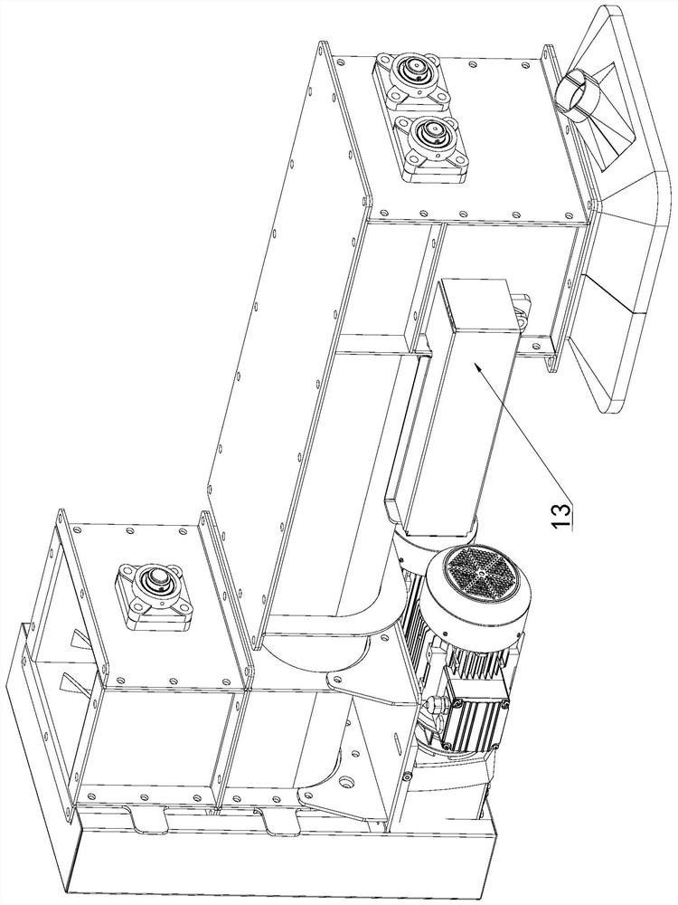
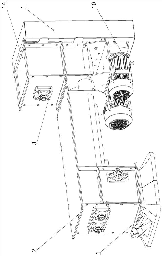
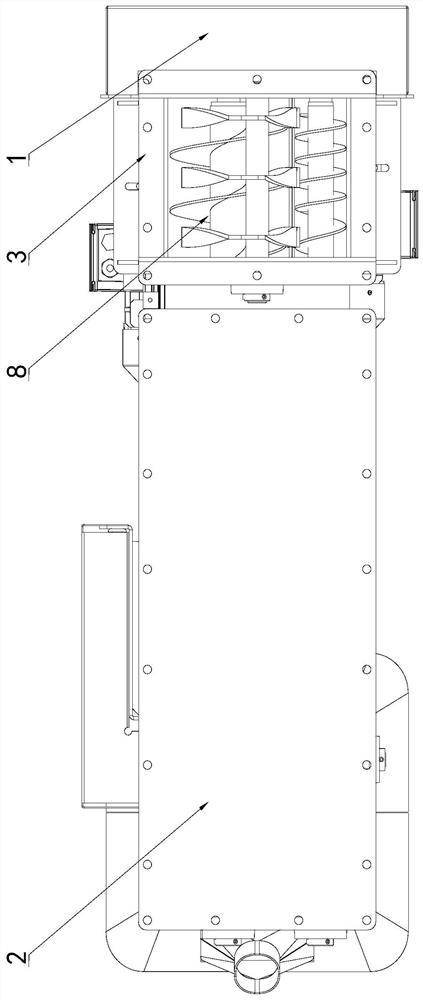
[0030] Such as Figure 1~4 An anti-oxidation system for molten aluminum in a furnace is shown, which includes a mounting frame 1 and a melting furnace body arranged on the mounting frame 1; the melting furnace body includes an upper furnace body 2 and the upper furnace body 2 A connected lower furnace body 3; the upper furnace body 2 is located above the lower furnace body 3; a first cavity is provided in the lower furnace body 3; The partition 4 for the lifting movement of the installation frame 1; the partition 4 divides the first cavity into a compression space arranged up and down and isolated from each other and a liquid storage space 5 for storing aluminum liquid; the partition 4 An air layer 6 is formed between the aluminum liquid, and the position corresponding to the air layer 6 on the lower furnace body 3 is provided with an air inlet and an exhaust port, and the air inlet is connected to the external connection for conveying inert gas. The device is connected.

[...

Embodiment 2

[0039] The second embodiment is a further description of the above embodiments. It should be understood that this embodiment includes all the aforementioned technical features and is further specifically described as:

[0040] Such as Figure 1~4An anti-oxidation system for molten aluminum in a furnace is shown, which includes a mounting frame 1 and a melting furnace body arranged on the mounting frame 1; the melting furnace body includes an upper furnace body 2 and the upper furnace body 2 A connected lower furnace body 3; the upper furnace body 2 is located above the lower furnace body 3; a first cavity is provided in the lower furnace body 3; The partition 4 for the lifting movement of the installation frame 1; the partition 4 divides the first cavity into a compression space arranged up and down and isolated from each other and a liquid storage space 5 for storing aluminum liquid; the partition 4 An air layer 6 is formed between the aluminum liquid, and the position corre...


PUM


Abstract

The invention discloses an anti-oxidation system for molten aluminum in a furnace. The anti-oxidation system comprises a mounting frame and a smelting furnace body arranged on the mounting frame. Thesmelting furnace body comprises an upper furnace body and a lower furnace body communicating with the upper furnace body. The upper furnace body is located above the lower furnace body. A first cavityis formed in the lower furnace body. A partition plate capable of doing lifting motion relative to the mounting frame is arranged in the first cavity. The first cavity is divided into a compression space and a liquid storage space through the partition plate, wherein the compression space and the liquid storage space are arranged up and down and isolated from each other, and the liquid storage space is used for storing the molten aluminum. An air layer is formed between the partition plate and the molten aluminum. An air inlet and an exhaust port are formed in the positions, corresponding tothe air layer, of the lower furnace body, and the air inlet communicates with external equipment used for conveying inert gas. The anti-oxidation system has the beneficial effects that the anti-oxidation system is simple in structure and low in manufacturing cost, the molten aluminum anti-oxidation problem is solved, the cost is reduced, and the production profit is increased.

Description

technical field [0001] The invention relates to the technical field of non-ferrous metal smelting, in particular to an anti-oxidation system for molten aluminum in a furnace. Background technique [0002] With the rapid development of the industrial economy, the demand for aluminum alloys is increasing. Most of the smelting equipment used in the production of aluminum alloys in the prior art uses fuel reverberatory furnaces. The aluminum or aluminum alloy melt and solid material are directly heated by means of high-temperature flue gas convection and furnace wall and roof radiation heat transfer. Typical or common existing technologies include: [0003] For example, CN106595305A discloses a smelting furnace and an aluminum smelting method, which includes a preheating chamber for preheating aluminum raw materials, a melting chamber for melting the preheated aluminum raw materials, and a burner. Biomass particles are used as a fuel burner, and the flue gas generated by the b...

Claims


Application Information

Patent Timeline
Patent Type & Authority Applications(China)
IPC IPC(8): F27B14/04F27B14/08F27D7/02F27D27/00
CPCF27B14/04F27B14/08F27D7/02F27D27/00F27B2014/0875F27M2003/13
Inventor 周思根蔡知之李小欣刘翼玮刘荣超
Owner 佛山市三水凤铝铝业有限公司
Why Eureka
Try Eureka