Frequency converter with automatic temperature control and heat radiation function

An automatic temperature control and frequency converter technology, applied in temperature control, non-electric variable control, instruments, etc., can solve the problems of uneven and insufficient heat dissipation of frequency converters, reduce failure rates, improve heat dissipation, and ensure normal operation Effect

Active Publication Date: 2017-02-08
重庆科川电气有限公司
View PDF8 Cites 0 Cited by
  • Summary
  • Abstract
  • Description
  • Claims
  • Application Information

AI Technical Summary

Problems solved by technology

[0004] The purpose of the present invention is to provide a frequency converter with automatic temperature control and

Method used


Image

  • Frequency converter with automatic temperature control and heat radiation function

Examples


Example Embodiment

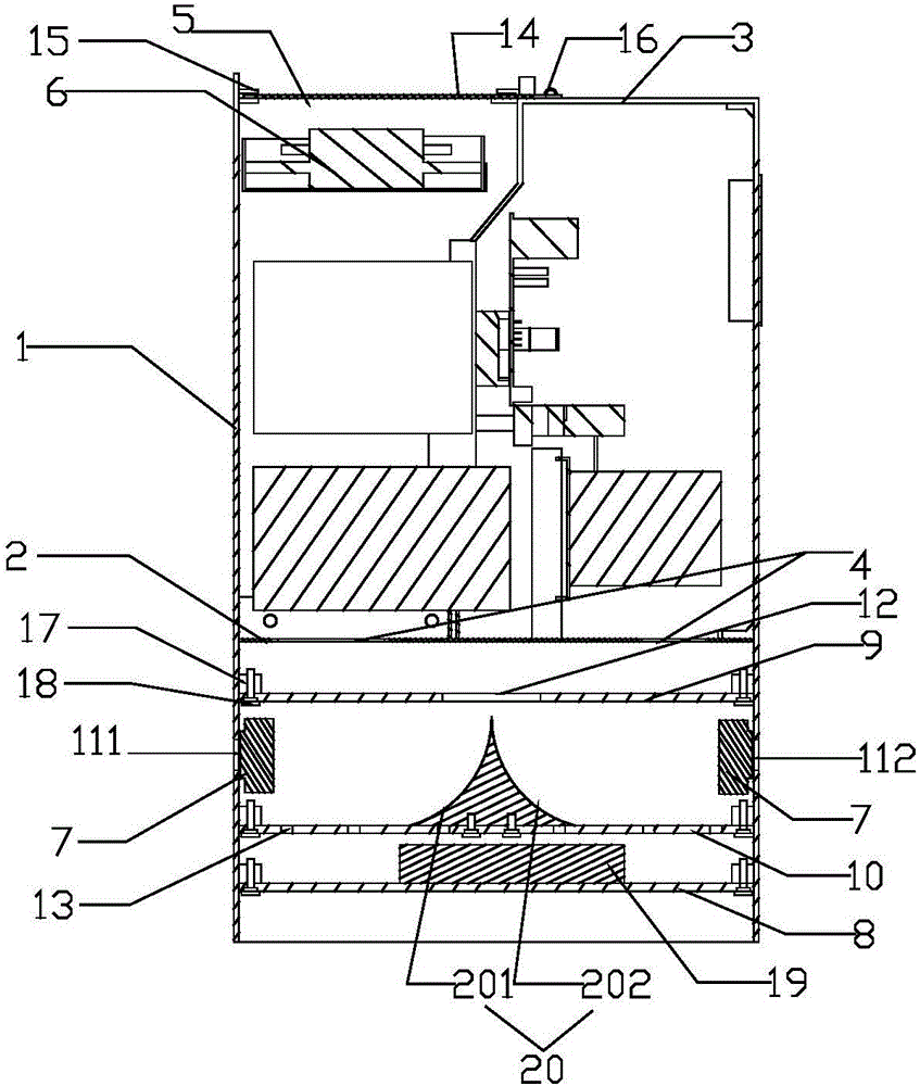
[0017] The present invention will be further described below with reference to the drawings and embodiments.

[0018] As shown in the figure, the waterproof and dustproof frequency converter of this embodiment includes a control cabinet 1, an air inlet 4 is provided on the bottom plate 2 of the control cabinet 1, and an air outlet 5 is provided on the top plate 3 of the control cabinet 1. The air outlet 5 is provided with an axial fan 6, and an upper partition 9 and a lower partition 10 are arranged from top to bottom on the lower part of the bottom plate 2. Between the upper and lower partitions, inlets are respectively provided on the two side walls of the control cabinet. The air hole 11 is equipped with a cold air device 7 at the air inlet 11, the cold air device 7 is electrically connected to the cold air device controller 19, the cooling device controller 19 is installed on the sealing plate 8, and the cooling device controller 19 is electrically connected to The temperatur...


PUM


Abstract

A frequency converter with an automatic temperature control and heat radiation function comprises a control cabinet, a cooling device, a cooling device controller, a temperature sensor and an axial flow fan. Through temperature detection of the temperature sensor to the frequency converter, the temperature sensor transmits information to the cooling device controller. The cooling device controller starts the cooling device for cooling air which enters the frequency converter, thereby performing a better heat radiation function, ensuring normal operation of the frequency converter, preventing component damage in the frequency converter, and reducing fault rate.

Description

technical field [0001] The invention relates to a radiator, in particular to a frequency converter with automatic temperature control and heat dissipation. Background technique [0002] With the rapid development of modern electric power technology and computer control technology, the technical revolution of electric drive has been promoted. The frequency converter is one of the important electrical appliances widely used in the industrial field. The frequency converter is composed of a rectifier circuit, an intermediate circuit, an inverter and a control circuit. The frequency converter is a key component of the energy-saving control link and generates a large amount of heat. Therefore, the control cabinet of the frequency converter is equipped with ventilation and cooling channels and ventilation and cooling holes. [0003] However, long-term operation will lead to a great increase in heat. If the inverter is not cooled in time, it will easily lead to damage to electronic...

Claims


Application Information

Patent Timeline
IPC IPC(8): G05D23/20
CPCG05D23/20
Inventor 曾伯军
Owner 重庆科川电气有限公司
Why Eureka
Try Eureka