Medical push-pull type needless infusion connector

A push-pull, infusion tube technology, applied in the direction of introduction of equipment into the body, etc., can solve the problems of increasing the workload and psychological burden of medical staff, large sliding resistance between the stop clip and the extension tube, and pulling the catheter assembly away from the patient's body, etc. To save patient costs, avoid accidental injury, and ensure the effect of sealing

Pending Publication Date: 2017-02-15
欧阳小青
View PDF6 Cites 0 Cited by
  • Summary
  • Abstract
  • Description
  • Claims
  • Application Information

AI Technical Summary

Problems solved by technology

This kind of operation is cumbersome and there will still be a space that cannot be filled by the sealing fluid, and negative pressure will still be generated. In order to make up for this deficiency, it is customary to put the stop clip on after clamping the extension tube. The catheter assembly slides in the direction, so that the extension tube is gradually squeezed, and the liquid in the extension tube is squeezed into the lumen of the indwelling catheter to drive out the backflow blood. However, when the stop clip and the extension tube are clamped, the sliding resistance is large. The extension tube is elongated and thinner. During the indwelling period, the catheter assembly is pulled out many times. In severe cases, the extension tube will be broken and cause bleeding. In addition, the catheter assembly is stuck on the patient's body. The length of the extension tube is limited. Inadvertently, the catheter assembly will be pulled away from the patient's body. In order to avoid the above-mentioned accidents, the medical staff should be cautious when operating. Sometimes the length of the stop clip is not enough to completely drive the blood out of the catheter. Therefore, this operation method Invisibly increase the workload and psychological burden of medical staff

Method used


Image

  • Medical push-pull type needless infusion connector
  • Medical push-pull type needless infusion connector
  • Medical push-pull type needless infusion connector

Examples


Embodiment Construction

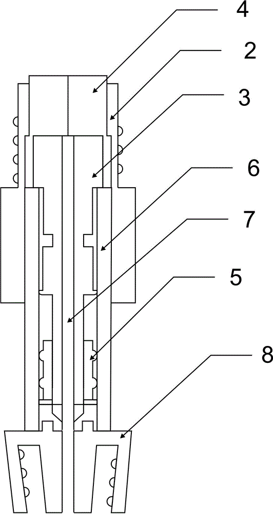
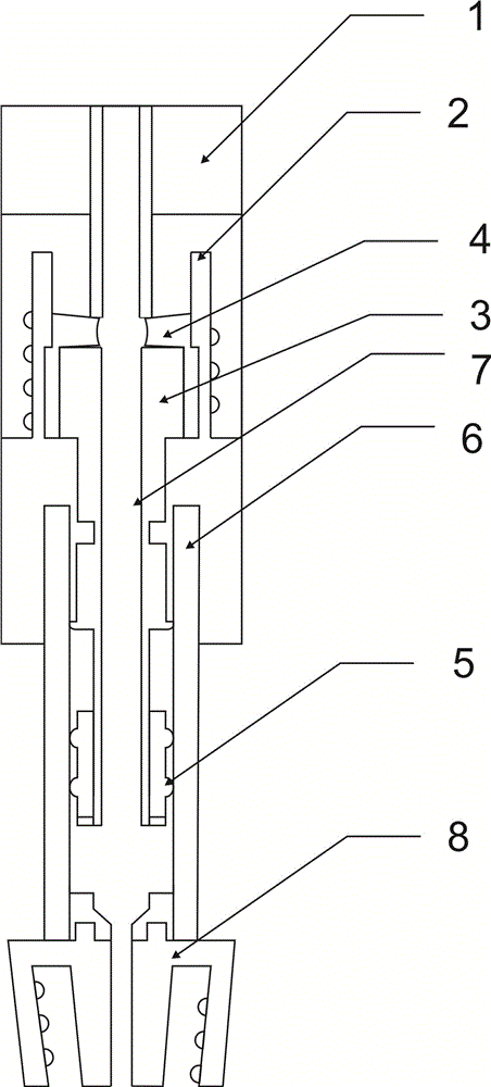
[0025] Such as figure 1 As shown, the present invention includes a needle-free infusion head and a needle-free infusion connector, the needle-free infusion head and the needle-free infusion connector are threadedly connected, the needle-free infusion connector is connected with a push rod, the push rod is placed in the infusion tube, and the infusion tube is connected to the Lu Er connector connection.

[0026] The outside of the needle-free infusion connector is threaded, and the top has an infusion through hole, which is convenient for the needle-free infusion head to be connected with the thread and is easy to fix.

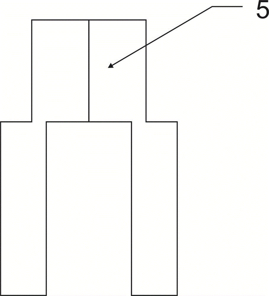
[0027] There is a closed ring at the bottom of the push rod, and the closed ring is a double-ring closed ring. The closed ring structure is to ensure that the space above and below the closed ring cannot be connected when the push rod is advanced or pulled up, so as to ensure the effect of pushing or pulling the push rod.

[0028] The part of the push rod exte...


PUM


Abstract

The invention provides a medical push-pull type needless infusion connector. The medical push-pull type needless infusion connector comprises a needless infusion head and a needless infusion connector body, wherein the needless infusion head and the needless infusion connector body are connected through threads, the needless infusion connector body is connected with a push rod, the push rod is placed in an infusion tube, and the infusion tube is connected with a Ruhr connector. The medical push-pull type needless infusion connector is simple in structure and easy to operate, after the needless infusion head is inserted from a through hole of the needless infusion connector body for squeezing closing rubber, the two pieces closing rubber deform, and after an infusion passage is formed after the deformation, the infusion can be carried out. According to the medical push-pull type needless infusion connector, due to the adoption of the needless connection structure, the accidental injuries possibly caused to the nurses and patients by the transdermal needle can be avoided, and the problem that when the transdermal needle is used for infusion, after the infusion is finished, during the process of drawing out the transdermal needle, blood can backwards flow into a catheter of an indwelling needle is solved.

Description

technical field [0001] The invention relates to medical equipment, in particular to an anti-thrombosis needle-free infusion joint used for connecting with an extracorporeal catheter of an indwelling needle. Background technique [0002] In clinical medicine, when patients need multiple infusions, indwelling catheters are usually used in vitro, and the connection methods between indwelling catheters and infusion sets are divided into needle connection and needleless connection. In the prior art, there is a connection method with a needle. The medical infusion connector is composed of a connecting seat and a connector body affixed thereto. This connector body is usually also called a heparin cap. The needle tube of the infusion set is inserted through the sealing rubber plug on the top of the connector body. At the end of the infusion, when the needle tube of the infusion set is pulled out, the space occupied by the needle tube is close to a vacuum, which creates negative pre...

Claims


Application Information

Patent Timeline
Patent Type & Authority Applications(China)
IPC IPC(8): A61M5/14
CPCA61M5/14A61M2005/1401
Inventor 欧阳小青
Owner 欧阳小青
Why Eureka
Try Eureka