AI technical title is built by Patsnap AI team. It summarizes the technical point description of the patent document.
A technology of stencil printing machine and stamping die, applied in the field of stencil printing machine, can solve the problems of different printing depth, unclear handwriting, laborious and other problems, and achieve the effect of good effect and uniform force
Active Publication Date: 2017-02-15
张锁柱
View PDF15 Cites 7 Cited by
Summary
Abstract
Description
Claims
Application Information
AI Technical Summary
This helps you quickly interpret patents by identifying the three key elements:
Problems solved by technology
Method used
Benefits of technology
Problems solved by technology
The disadvantage is that it is laborious to press for a long time, and the pressure on the stamp mold is uneven, which makes the pressed prints have different depths and the writing is not clear.
Method used
Image
Click on the blue label to locate the original text in one second.
Reading with bidirectional positioning of images and text.
Examples
Embodiment 1
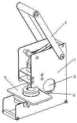
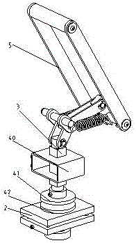
[0027] Such as Figure 1~4 As shown, a stamping machine, it includes:
[0028] base 1;
[0029] Supporting platform 2, described supporting platform 2 is installed on the base 1;
[0030] An action shaft 3, the action shaft 3 is slidingly fitted on the base 1, and the action shaft 3 can move up and down on the base 1;
[0031] die, the die includes an upper die 41 and a lower die 42, the upper die 41 is connected to the lower end of the action shaft 3, and the lower die 42 is installed on the support table 2;
[0032] A driving mechanism, the driving mechanism is movably connected with the action shaft 3, so that when the driving mechanism operates, the action shaft 3 moves up and down on the base 1, thereby driving the upper die 41 away from or toward the lower die 42 to realize embossing on the paper between the upper stamp 41 and the lower stamp 42.
[0033] Wherein, the guiding of the action shaft 3 is realized by the following structure: the action shaft 3 is a square...
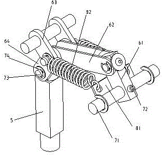
Embodiment 2
[0044] The structure of this embodiment is basically the same as that of Embodiment 1. The difference is: the specific structure of the driving mechanism. 92, reciprocating rod 93, pivot rod 94 and transition link 95, the power source drives the eccentric wheel 91 to rotate, the bearing 92 is rotatably supported on the eccentric wheel 91, the reciprocating rod 93 One end is hinged with the bearing 92, the other end of the reciprocating rod 93, one end of the pivot rod 94 and one end of the transition link 95 are hinged together, the other end of the pivot rod 94 is pivotally connected to the base 1, The other end of the transition link 95 is hinged to the action shaft 3 .
[0045] The working principle of this embodiment is as follows:
[0046] When the motor 10 rotates, the gear box 20 shifts and outputs an appropriate speed to drive the eccentric wheel 91, and the bearing 92 cooperates with the eccentric wheel 91 to push the reciprocating rod 93 to move back and forth, and ...
PUM
Abstract
The invention discloses a steel printing machine which comprises a base, a supporting table installed on the base, an acting shaft which is assembled on the base in a sliding manner and can move vertically on the base, a printing die comprising an upper printing die body and a lower printing die body, and a driving mechanism. The upper printing die body is connected to the lower end of the acting shaft, and the lower printing die body is installed on the supporting table. The driving mechanism is movably connected with the acting shaft so that when the driving mechanism acts, the acting shaft moves vertically on the base, and therefore the upper printing die body is driven to move in the direction away from the lower printing die body or in the direction towards the lower printing die body, and impressing of paper between the upper printing die body and the lower printing die body is achieved. The steel printing machine can be used for well impressing the paper, in addition, labor is saved, the steel printing writing effect is good, and stress is even.
Description
technical field [0001] The invention relates to a stampingmachine. Background technique [0002] At present, the principle of the mechanical transmission structure in the stencil printing machine on the market is a simple lever type, which is fixed by one end of the long arm and a fulcrum. When the long arm is pressed, the protruding block at the front end of the long arm will take the fulcrum as the central axis Turn and press the stencil. The disadvantage is that it is laborious to press for a long time, and the pressure on the stamp mold is uneven, which makes the pressed prints have different depths and unclear writing. Contents of the invention [0003] The technical problem to be solved by the present invention is to overcome the defects of the prior art and provide a stencil printing machine, which can emboss paper well, save labor, have good stencil printing effect and uniform force. [0004] The technical scheme adopted by the present invention to solve the abo...
Claims
Application Information
Patent Timeline
Application Date:The date an application was filed.
Publication Date:The date a patent or application was officially published.
First Publication Date:The earliest publication date of a patent with the same application number.
Issue Date:Publication date of the patent grant document.
PCT Entry Date:The Entry date of PCT National Phase.
Estimated Expiry Date:The statutory expiry date of a patent right according to the Patent Law, and it is the longest term of protection that the patent right can achieve without the termination of the patent right due to other reasons(Term extension factor has been taken into account ).
Invalid Date:Actual expiry date is based on effective date or publication date of legal transaction data of invalid patent.

