
Automotive interior cooling system

A cooling system and automobile technology, applied in heating/cooling equipment, vehicle components, air handling equipment, etc., can solve the problems of adding a large burden to the automobile engine, reducing the efficiency of the automobile cooling system, and large energy consumption, etc., to achieve easy promotion, Simple structure and low energy consumption

Inactive Publication Date: 2017-02-15
LANZHOU UNIVERSITY
View PDF4 Cites 0 Cited by
  • Summary
  • Abstract
  • Description
  • Claims
  • Application Information

AI Technical Summary

Problems solved by technology

Nowadays, cars use the indoor air-conditioning system to realize cooling in summer and heating in winter, but due to the characteristics of the car air-conditioning system, it will add a greater burden to the car engine, resulting in a decrease in power and greater energy consumption of the car. The cooling water system of the car shares a fan with the cooling system of the car engine, and the operation of the car refrigeration system reduces the efficiency of the car cooling system

Method used


Image

  • Automotive interior cooling system

Examples


Embodiment 1

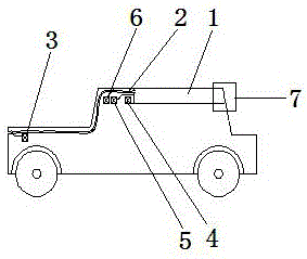
[0019] During the driving process of the car, due to the movement of the car, the outside air directly enters the ventilation duct 2 of the system from the front of the car, and at the same time controls the small water pump 4 to spray water to the evaporative heat exchanger 1, and the water evaporates to produce water vapor under the action of natural wind Discharge quickly and take away the heat. During the whole process, the small motor 3 controls the valve on the ventilation pipe 2 to adjust the air intake, and the control system controls the small water pump 4 to adjust the water spray, and finally achieves the purpose of adjusting the indoor temperature.

Embodiment 2

[0021] When the car is parked, due to the large resistance of external air entering and circulating in the system, the purpose of evaporative cooling cannot be achieved. The control system controls the small blower 5 to supply air to the evaporative heat exchanger 1, and the small water pump 4 sprays water together. Under this condition, the evaporative cooling is promoted to achieve the purpose of reducing the indoor temperature.

Embodiment 3

[0023] When the car is parked or running, the roof of the car will generate a higher temperature under the sun. When the small water pump 4 sprays water to the evaporative heat exchanger 1, the water on the surface of the evaporative heat exchanger will be evaporated quickly, and the water vapor inside and outside the car will evaporate quickly. Under the action of pressure, an outward circulation airflow is formed to achieve the purpose of reducing the indoor temperature.


PUM


Abstract

Disclosed is an automotive interior cooling system. The automotive interior cooling system comprises an automotive body, an evaporation heat exchanger, a ventilating duct, small motors, a small water pump, a small air feeder, a small water tank and a control system. The small motors are arranged at the front end of the automotive body, the ventilating duct, the small water pump and the small air feeder are arranged in the automotive body, and the evaporation heat exchanger is further arranged on the top of the automotive body. The small water tank is connected with the small water pump, the small water pump is connected with the evaporation heat exchanger, the ventilating duct is communicated with the evaporation heat exchanger, and an air outlet hole or exhaust gap is formed in the rear end of the evaporation heat exchanger, and communicated with the exterior. According to the automotive interior cooling system, due to the facts that water evaporation cooling is utilized to conduct cold supply, and only three small motors are needed by the whole system to provide the energy, compared with an existing automotive cooling system, the automotive interior cooling system has the advantage that the energy consumption is greatly reduced. Due to the fact that radiant cooling is conducted on the interior through the evaporation heat exchanger on an automotive roof, compared with the convection mode of the existing cooling system, the system has the advantage that a user can feel more comfortable.

Description

technical field [0001] The invention relates to the field of automobile refrigeration, in particular to an automobile indoor cooling system, which uses evaporative cooling technology to cool the automobile interior. Background technique [0002] With the development of society, automobiles are gradually popularized, and improving the comfort of the interior environment of automobiles has become one of the goals of the development of the automobile industry. Nowadays, cars use the indoor air-conditioning system to realize cooling in summer and heating in winter, but due to the characteristics of the car air-conditioning system, it will add a greater burden to the car engine, resulting in a decrease in power and greater energy consumption of the car. The cooling water system of the car shares a fan with the cooling system of the car engine, and the operation of the car refrigeration system reduces the efficiency of the car cooling system. Contents of the invention [00...

Claims


Application Information

Patent Timeline
IPC IPC(8): B60H1/32
CPCB60H1/3202
Inventor 王厚成焦继宗
Owner LANZHOU UNIVERSITY
Learn More