Nozzle block, air spinning device and spinning machine

A technology of open-end spinning and nozzle block, applied in spinning machine, open-end spinning machine, continuous winding spinning machine, etc., can solve the problem of high yarn tension and achieve the effect of suppressing high tension

Active Publication Date: 2020-05-12
MURATA MASCH LTD
View PDF9 Cites 0 Cited by
  • Summary
  • Abstract
  • Description
  • Claims
  • Application Information

AI Technical Summary

Problems solved by technology

[0004] However, if the above-mentioned combination is to be achieved, the tension acting on the yarn may be too high depending on the type of fiber.

Method used


Image

  • Nozzle block, air spinning device and spinning machine
  • Nozzle block, air spinning device and spinning machine
  • Nozzle block, air spinning device and spinning machine

Examples


Embodiment Construction

[0025] Hereinafter, embodiments of the present invention will be described in detail with reference to the drawings. In addition, in each figure, the same reference numerals are assigned to the same or corresponding parts, and overlapping descriptions will be omitted.

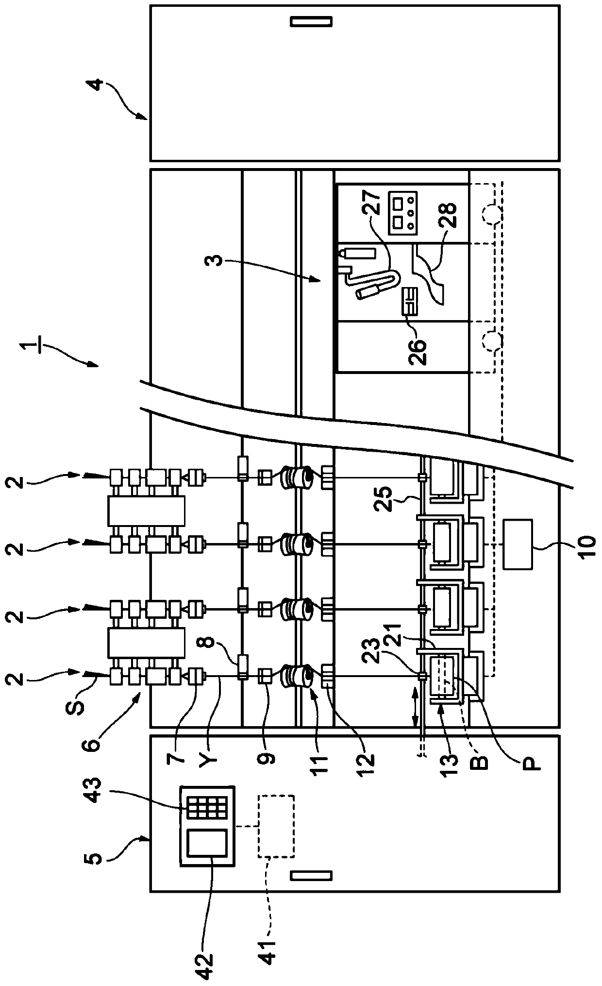
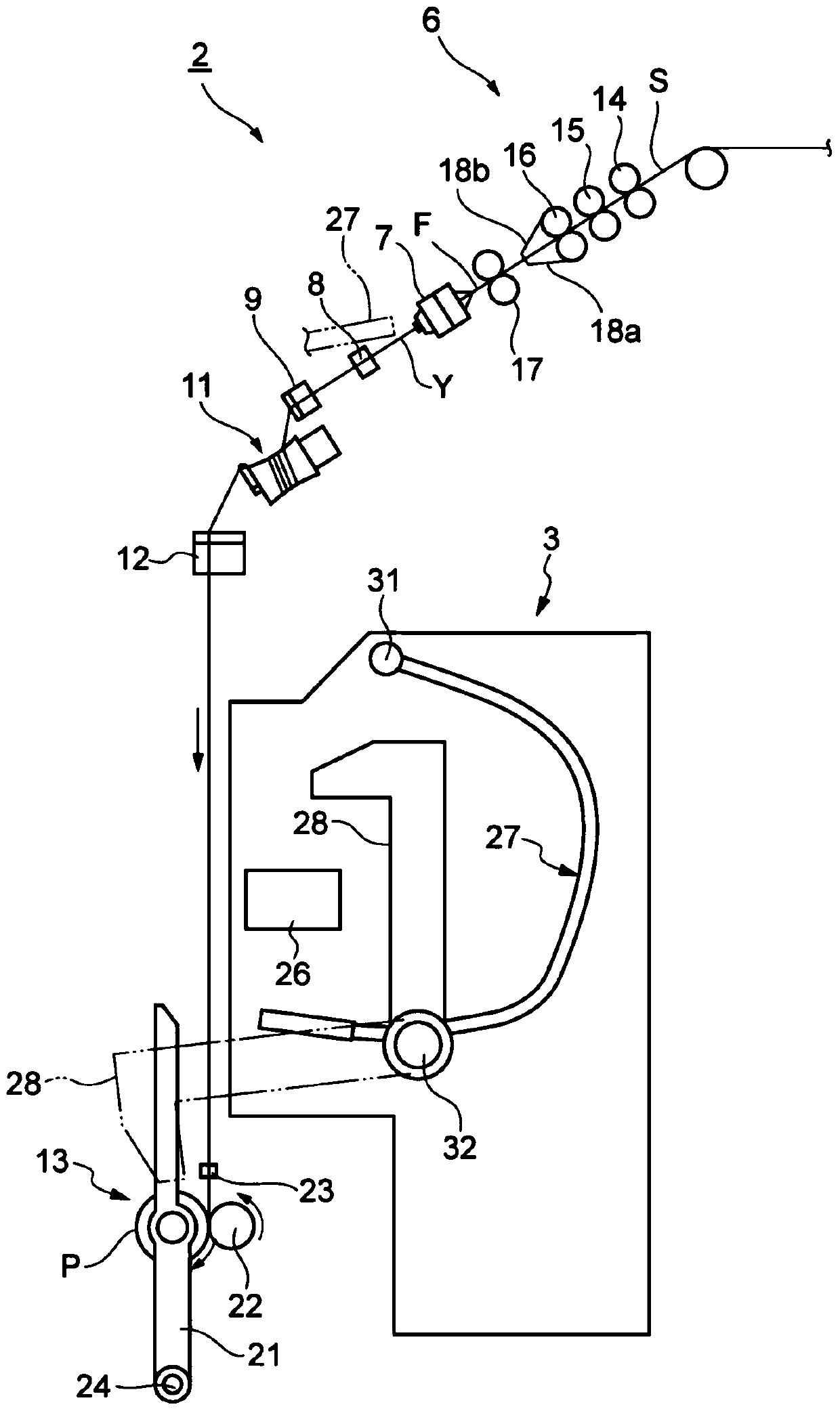
[0026] Such as figure 1 As shown, the spinning machine 1 includes a plurality of spinning units 2 , a yarn joining cart 3 , a doffing cart (not shown), a first end frame 4 , and a second end frame 5 . A plurality of spinning units 2 are arranged in a row. Each spinning unit 2 produces a yarn Y and winds it into a package P. The yarn joining cart 3 performs a yarn joining operation in a certain spinning unit 2 when the yarn Y is cut in the spinning unit 2 or the yarn Y is cut for some reason. The doffing trolley doffs the package P and supplies the new bobbin B to the spinning unit 2 when the package P in one of the spinning units 2 becomes full.

[0027] The first end frame 4 accommodates a recovery device ...


PUM


Abstract

In a nozzle block (60), a first space (64), a second space (66), and a third space (67) are aligned from a first side toward a second side in a predetermined direction. The second space (66) is spread at a second inner surface tapered angle from the first side toward the second side. The third space (67) is spread at a third inner surface tapered angle greater than the second inner surface tapered angle from the first side toward the second side. A height (H1) of the first space (64) is a value greater than or equal to 3 mm and smaller than or equal to 8 mm. A height (H2) of the second space (66) is a value greater than or equal to 30% and smaller than or equal to 50% of a sum of the height (H2) and a height (H3) of the third space (67).

Description

technical field [0001] The invention relates to a nozzle block, an air spinning device and a spinning machine. Background technique [0002] There is known an air spinning device comprising: a nozzle block for twisting introduced fibers by a swirling air flow, a fiber inlet for introducing the twisted fibers, and a passage for leading out fibers introduced from the fiber inlet to the outside. The hollow guide shaft unit (for example, refer to Japanese Patent Laid-Open No. 2009-001935, Japanese Patent Laid-Open No. 2003-193339). [0003] In an air-jet spinning device, both ensuring stable winding properties (the degree of twisting of fibers) and improving the spinning speed (yarn production speed) are sometimes required. [0004] However, in order to achieve the above-mentioned combination, depending on the type of fiber, the tension acting on the yarn may be too high. Contents of the invention [0005] Therefore, an object of the present invention is to provide a nozzle ...

Claims


Application Information

Patent Timeline
Patent Type & Authority Patents(China)
IPC IPC(8): D01H1/115D01H4/02
CPCD01H1/115D01H4/02
Inventor 森田晃弘
Owner MURATA MASCH LTD
Why Eureka
Try Eureka