Sliding-friction pendulum combined shock-insulation layer with ultra-large bottom surface

A sliding friction and seismic isolation layer technology, applied in the direction of earthquake resistance, building components, building types, etc., can solve the problem that the isolation bearing is difficult to meet the super earthquake resistance performance of the isolation building, and achieve the obvious isolation effect and reduce the seismic effect. , the effect of not easy to reverse

Active Publication Date: 2017-02-15
HARBIN INST OF TECH
View PDF7 Cites 7 Cited by
  • Summary
  • Abstract
  • Description
  • Claims
  • Application Information

AI Technical Summary

Problems solved by technology

[0003] In order to solve the problem that the existing seismic isolation bearings are difficult to meet the anti-super-large earthquake performance of high-level waterproof and seismic-isolation buildings, the invention provides a super-large bottom surface sliding friction pendulum combined seismic isolation layer

Method used


Image

  • Sliding-friction pendulum combined shock-insulation layer with ultra-large bottom surface
  • Sliding-friction pendulum combined shock-insulation layer with ultra-large bottom surface
  • Sliding-friction pendulum combined shock-insulation layer with ultra-large bottom surface

Examples


specific Embodiment approach 1

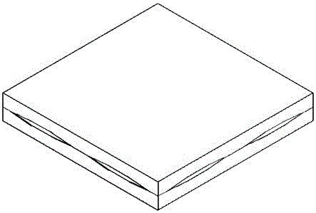
[0031] Specific implementation mode one: as Figure 1-4 As shown, the super-large bottom surface sliding friction pendulum combined shock-isolation layer of this embodiment is composed of an upper spherical shell layer 7, a lower spherical shell layer 2 and a sliding frame 8, wherein:

[0032] The lower surface of the lower spherical shell layer 2 is integrally poured with the concrete foundation or the lower structure 1, and the upper surface is provided with four arc-shaped spherical surfaces 14 with openings upward and at the same horizontal plane;

[0033] The upper surface of the upper spherical shell layer 7 is connected to the structural column of the upper structure, and the lower surface is provided with four arc-shaped spherical surfaces 14 with openings downward and on the same horizontal plane;

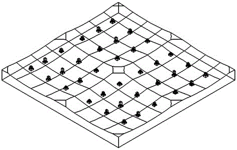
[0034] The openings of the upper spherical shell layer 7 and the lower spherical shell layer 2 are relatively arranged to form four flat cavities, and a sliding frame 8 is...

specific Embodiment approach 2

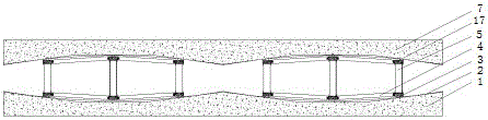
[0038] Specific implementation mode two: as Figure 5-12 As shown, the structure of the lower connection member 6 and the upper connection member 17 in this embodiment are the same. The cross section of the lower connecting member 6 is box-shaped, and the inside is filled with concrete and embedded with bolts 9 . The lower cover plate of the lower connecting member 6 is welded to the top of the slider 3, the side of the lower connecting member 6 is connected with the beam end angle plate 1 bolt connection and the welding of the flange and the I-shaped connecting beam 1 bolt welding, and the upper connecting member 17 is connected The cover plate is welded to the top of the slider 3, and the side part of the upper connecting member 17 is connected by a beam end angle plate 1 bolt connection and flange welding and an I-shaped connecting beam 1 bolt welding, forming a sliding frame 8 whose upper and lower surfaces are spherical as a whole . According to the design, it can also ...

specific Embodiment approach 3

[0042] Specific implementation mode three: as Figure 13-15 As shown, in this embodiment, the whole lower spherical shell layer 2 is formed by pouring concrete, and the specifications are compatible with the concrete foundation or the lower structure 1. Friction material; each arc-shaped spherical surface 14 is completely cut off at the overlapped part, ensuring that the movement of the sliding frame 8 is not blocked, and the edges and corners at the opening of the arc-shaped spherical surface 14 are ground to a smooth transition.

[0043] The lower surface of the lower spherical shell layer 2 is generally truncated, and the side surface of the truss is a corrugated galvanized profiled steel plate 15, which is vertically grooved. It is connected by welding and integrally poured with the concrete foundation or the substructure 1.


PUM


Abstract

The invention discloses a sliding-friction pendulum combined shock-insulation layer with an ultra-large bottom surface. The combined shock-insulation layer comprises an upper spherical shell layer, a lower spherical shell layer and sliding frames. Four arc-shaped spherical faces are arranged on the upper surfaces of the lower spherical shell layer. Four arc-shaped spherical faces are arranged on the lower surface of the upper spherical shell layer. Each sliding frame is composed of a plurality of sliding blocks, upper connecting components, lower connecting components, connecting beams and sliding frame columns, wherein the sliding frame columns are connected between the upper connecting components and the lower connecting components, and the lateral portions of the upper connecting components and the lateral portions of the lower connecting components are connected with the connecting beams. The upper end surfaces of the upper connecting components and the lower end surfaces of the lower connecting components are welded to the sliding blocks. The sliding frames are in overlap joint with the arc-shaped spherical faces of the upper spherical shell layer and the arc-shaped spherical faces of the lower spherical shell layer through the sliding blocks. According to the sliding-friction pendulum combined shock-insulation layer with the ultra-large bottom surface, the sliding frames are formed through connection of the sliding blocks, and the integral shock-insulation layer is formed by the sliding frames, the upper spherical shell layer and the lower spherical shell layer; and the span of the shock-insulation layer is quite large, the allowable deformation, in the horizontal direction, of the shock-insulation layer is far larger than that of a shock-insulation support, and the requirement for horizontal deformation of the shock-insulation layer under an extremely-powerful earthquake can be completely met.

Description

technical field [0001] The invention belongs to the technical field of shock absorption and isolation of building structures, and relates to a combined shock isolation layer of a sliding friction pendulum with a super large bottom surface. Background technique [0002] Seismic isolation technology is an outstanding research achievement in the field of structural seismicity in the past 50 years, and has been widely used in my country. Seismic isolation measures can make the superstructure in an elastic or weakly nonlinear state under the action of a large earthquake, reducing the seismic response of the superstructure. However, due to its clear failure mode, the deformation of the isolation layer and the overturning of the overall structure are prominent problems of the isolation structure under the action of a super large earthquake. Common seismic isolation devices for building structures include rubber bearings and friction pendulum bearings, whose horizontal deformation ...

Claims


Application Information

Patent Timeline
Patent Type & Authority Applications(China)
IPC IPC(8): E04B1/36E04B1/98E04H9/02
CPCE04B1/36E04H9/021E04H9/025
Inventor 欧进萍武沛松关新春
Owner HARBIN INST OF TECH
Why Eureka
Try Eureka