Sliding friction pendulum combined shock-isolation layer with super large bottom surface
A sliding friction, seismic isolation layer technology, applied in the direction of earthquake resistance, building components, building types, etc., can solve the problem that the isolation bearing is difficult to meet the super earthquake resistance performance of the isolation building, and achieve the obvious isolation effect and reduce the seismic effect. , the effect of not easy to reverse
- Summary
- Abstract
- Description
- Claims
- Application Information
AI Technical Summary
Problems solved by technology
Method used
Image
Examples
specific Embodiment approach 1
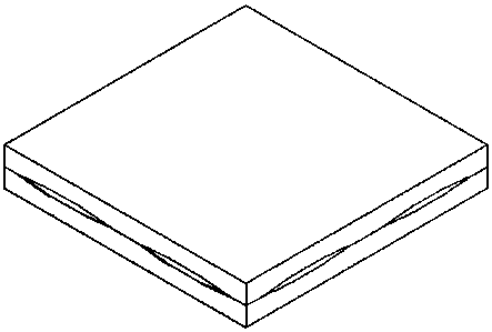
[0031] Specific implementation mode one: as Figure 1-4 As shown, the super-large bottom surface sliding friction pendulum combined shock-isolation layer of this embodiment is composed of an upper spherical shell layer 7, a lower spherical shell layer 2 and a sliding frame 8, wherein:
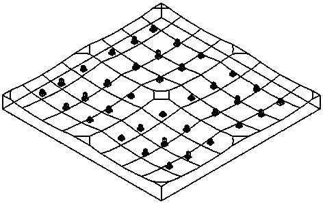
[0032] The lower surface of the lower spherical shell layer 2 is integrally poured with the concrete foundation or the lower structure 1, and the upper surface is provided with four arc-shaped spherical surfaces 14 with openings upward and at the same horizontal plane;
[0033] The upper surface of the upper spherical shell layer 7 is connected to the structural column of the upper structure, and the lower surface is provided with four arc-shaped spherical surfaces 14 with openings downward and on the same horizontal plane;
[0034] The openings of the upper spherical shell layer 7 and the lower spherical shell layer 2 are relatively arranged to form four flat cavities, and a sliding frame 8 is...
specific Embodiment approach 2
[0038] Specific implementation mode two: as Figure 5-12 As shown, the structure of the lower connection member 6 and the upper connection member 17 in this embodiment are the same. The cross section of the lower connecting member 6 is box-shaped, and the inside is filled with concrete and embedded with bolts 9 . The lower cover plate of the lower connecting member 6 is welded to the top of the slider 3, the side of the lower connecting member 6 is connected with the beam end angle plate 1 bolt connection and the welding of the flange and the I-shaped connecting beam 1 bolt welding, and the upper connecting member 17 is connected The cover plate is welded to the top of the slider 3, and the side part of the upper connecting member 17 is connected by a beam end angle plate 1 bolt connection and flange welding and an I-shaped connecting beam 1 bolt welding, forming a sliding frame 8 whose upper and lower surfaces are spherical as a whole . According to the design, it can also ...
specific Embodiment approach 3
[0042] Specific implementation mode three: as Figure 13-15 As shown, in this embodiment, the whole lower spherical shell layer 2 is formed by pouring concrete, and the specifications are compatible with the concrete foundation or the lower structure 1. Friction material; each arc-shaped spherical surface 14 is completely cut off at the overlapped part, ensuring that the movement of the sliding frame 8 is not blocked, and the edges and corners at the opening of the arc-shaped spherical surface 14 are ground to a smooth transition.
[0043] The lower surface of the lower spherical shell layer 2 is generally truncated, and the side surface of the truss is a corrugated galvanized profiled steel plate 15, which is vertically grooved. It is connected by welding and integrally poured with the concrete foundation or the substructure 1.
PUM
 Abstract
Description
Claims
Application Information
 - R&D
- Intellectual Property
- Life Sciences
- Materials
- Tech Scout
- Unparalleled Data Quality
- Higher Quality Content
- 60% Fewer Hallucinations
Browse by: Latest US Patents, China's latest patents, Technical Efficacy Thesaurus, Application Domain, Technology Topic, Popular Technical Reports.
© 2025 PatSnap. All rights reserved.Legal|Privacy policy|Modern Slavery Act Transparency Statement|Sitemap|About US| Contact US: help@patsnap.com


