A kind of drill pipe grouting method

A drill pipe and self-grouting technology, which is applied in earthwork drilling, wellbore/well parts, construction, etc., can solve the problems of high grouting cost, time-consuming and labor-intensive work, and large engineering volume, so as to reduce the engineering volume and prevent blowback , The effect of reducing the cost of grouting

Active Publication Date: 2019-05-21
CHENGDU ZHUOXIN IND
View PDF10 Cites 0 Cited by
  • Summary
  • Abstract
  • Description
  • Claims
  • Application Information

AI Technical Summary

Problems solved by technology

However, in the prior art represented by this patent document, when the mud is being circulated, a large amount of mud needs to be poured into the drill pipe through the grouting device on the ground. The device pours mud into the drill pipe. After filling, remove the grouting device and put in the next section of drill pipe. Only by repeating this can the drilling action be completed. The amount of work is very large, time-consuming and laborious, and the cost of grouting is quite high

Method used


Image

  • A kind of drill pipe grouting method
  • A kind of drill pipe grouting method
  • A kind of drill pipe grouting method

Examples


Embodiment 1

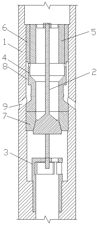
[0052] see figure 1 , a drill pipe grouting method, comprising the following steps:

[0053] a. Connect the upper end of the back pressure valve to the drill pipe, and the lower end of the back pressure valve to the drilling tool;

[0054] b. Drilling tools and back pressure valves are lowered into the well, and the mud in the well flows back into the drill pipe from bottom to top through the self-grouting channel of the back pressure valve to complete the automatic grouting of the drill pipe;

[0055] c. For positive circulation of mud, the piston 5 in the back pressure valve moves down to block the mud return slot 8 and close the self-grouting channel.

[0056] This embodiment is the most basic implementation. The upper end of the back pressure valve is connected to the drill pipe, and the lower end of the back pressure valve is connected to the drilling tool; The self-grouting channel returns the mud in the well to the drill pipe from bottom to top to complete the automat...

Embodiment 2

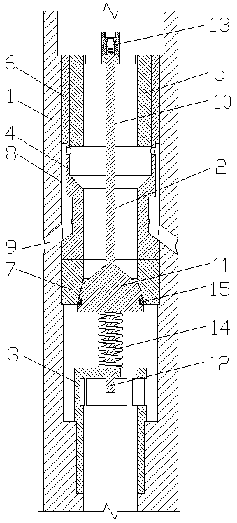
[0058] see figure 1 , a drill pipe grouting method, comprising the following steps:

[0059] a. Connect the upper end of the back pressure valve to the drill pipe, and the lower end of the back pressure valve to the drilling tool;

[0060] b. Drilling tools and back pressure valves are lowered into the well, and the mud in the well flows back into the drill pipe from bottom to top through the self-grouting channel of the back pressure valve to complete the automatic grouting of the drill pipe;

[0061] c. For positive circulation of mud, the piston 5 in the back pressure valve moves down to block the mud return slot 8 and close the self-grouting channel.

[0062] In the step a, the back pressure valve is a self-grouting back pressure valve, including the valve body 1, the valve core 2, the support seat 3 and the valve seat 4 arranged in the valve body 1, and the support seat 3 is located below the valve seat 4 , the valve body 1 is provided with a piston 5, the piston 5 is s...

Embodiment 3

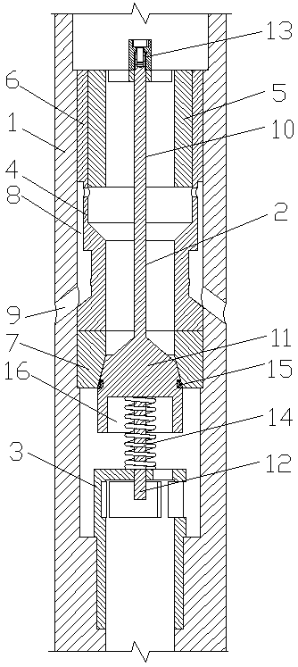
[0066] see figure 2 , a drill pipe grouting method, comprising the following steps:

[0067] a. Connect the upper end of the back pressure valve to the drill pipe, and the lower end of the back pressure valve to the drilling tool;

[0068] b. Drilling tools and back pressure valves are lowered into the well, and the mud in the well flows back into the drill pipe from bottom to top through the self-grouting channel of the back pressure valve to complete the automatic grouting of the drill pipe;

[0069] c. For positive circulation of mud, the piston 5 in the back pressure valve moves down to block the mud return slot 8 and close the self-grouting channel.

[0070]In the step a, the back pressure valve is a self-grouting back pressure valve, including the valve body 1, the valve core 2, the support seat 3 and the valve seat 4 arranged in the valve body 1, and the support seat 3 is located below the valve seat 4 , the valve body 1 is provided with a piston 5, the piston 5 is s...


PUM


Abstract

The invention discloses a grouting method for a drilling rod and belongs to the technical field of drilling. The grouting method is characterized by comprising the following steps: a, connecting the upper end of a back pressure valve with the drilling rod, and connecting the lower end of the back pressure valve with a drilling tool; b, tripping the drilling tool and the back pressure valve in a well, enabling slurry in the well to reflux into the drilling rod from bottom to top by a self-grouting channel of the back pressure valve, and finishing automatic grouting of the drilling rod; c, positively circulating the slurry, downwards moving a piston in the back pressure valve to block a slurry reflux groove hole and closing the self-grouting channel. According to the grouting method disclosed by the invention, reverse spraying of the slurry in the well can be prevented and the slurry in the well is enabled to automatically reflux into the drilling rod, and the operation that the grouting device is connected and pours the slurry into the drilling rod once a part of the drilling rod is laid down is not needed, so that the workload is greatly reduced, and the grouting cost is effectively reduced.

Description

technical field [0001] The invention relates to the technical field of drilling, in particular to a drill pipe grouting method. Background technique [0002] The back pressure valve is a device to prevent internal blowout during the drilling process. It is a check valve. The back pressure valve can effectively prevent the formation fluid from entering the drilling tool through the water hole of the drilling tool. [0003] The existing back pressure valve mainly includes a valve body, a support seat, a valve core and a valve seat. Its structural principle is that there is a conical movable valve core in the water eye of the tool. When installing, its large end faces down and the small end faces upward. When the mud flows from the water eye to the top and bottom, the flow resistance is small and it can pass through smoothly; When the mud flows from the bottom to the top of the drill string, the large end receives a greater thrust, which prompts the conical movable device to m...

Claims


Application Information

Patent Timeline
Patent Type & Authority Patents(China)
IPC IPC(8): E21B34/06E21B33/13
CPCE21B33/13E21B34/06E21B2200/05
Inventor 陈伦俊池振华邹益文卢伟
Owner CHENGDU ZHUOXIN IND
Why Eureka
Try Eureka