A Pilot Safety Valve System

A pilot-operated safety valve, pilot valve technology, applied in the direction of safety valve, lift valve, balance valve, etc., can solve the problems of safety valve without position indicator, no auxiliary isolation function, accurate action and low life, to reduce the first time. Leakage time, quick action, stable and reliable performance

Active Publication Date: 2019-01-11
NUCLEAR POWER INSTITUTE OF CHINA
View PDF8 Cites 1 Cited by
  • Summary
  • Abstract
  • Description
  • Claims
  • Application Information

AI Technical Summary

Problems solved by technology

[0005] The purpose of the present invention is to overcome the deficiencies of the prior art, to provide a pilot-operated safety valve system, to solve the problem that the existing safety valve has no position indicator, does not consider redundant design, has no auxiliary isolation function, and the sealing performance is not high. Problems of accuracy and low lifespan

Method used


Image

  • A Pilot Safety Valve System
  • A Pilot Safety Valve System
  • A Pilot Safety Valve System

Examples


Embodiment 1

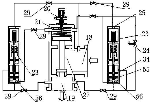
[0034] Such as figure 1 As shown, a pilot safety valve system of the present invention includes a main valve 22, a pilot valve 23 and a release valve 24. The main valve 22 is provided with a main valve inlet 18, a main valve outlet 19 and a flow channel hole 17. The pilot valve 23 It is provided with an upper end pressure sensing chamber inlet 25, a discharge hole 26, a relay valve inlet 27 and a relay valve outlet 28, and the main valve inlet 18 communicates with the upper end pressure sensing chamber inlet 25 of the pilot valve 23 through a pipeline and an isolation valve 29, and the flow The channel hole 17 communicates with the relay valve inlet 27 of the pilot valve 23 through the pipeline and the isolation valve 29, and the main valve outlet 19 of the main valve 22 is respectively connected with the discharge hole 26 of the pilot valve 23 and the relay valve outlet 28 through the pipeline and the isolation valve 29. connected.

[0035] When the system pressure is normal...

Embodiment 2

[0037] Such as figure 1 As shown, a pilot-operated safety valve system of the present invention, on the basis of Embodiment 1, the inlet of the release valve 24 communicates with the flow channel hole 17 through the pipeline and the isolation valve 29, and the outlet of the release valve 24 communicates with the main valve through the pipeline and the isolation valve 29. The valve outlet 19 is connected, and the release valve 24 realizes the forced release function by remotely manually controlling the opening and closing of the main valve 22 .

[0038] When the system requires manual remote forced pressure relief, the power supply of the release valve 24 is turned on, and the disc of the release valve 24 is pulled apart under the action of electromagnetic force, and the pressure medium in the piston chamber 21 of the main valve is released through the release valve 24 to make the main valve The pressure in the piston chamber 21 decreases, and the piston 7 of the main valve 22 ...

Embodiment 3

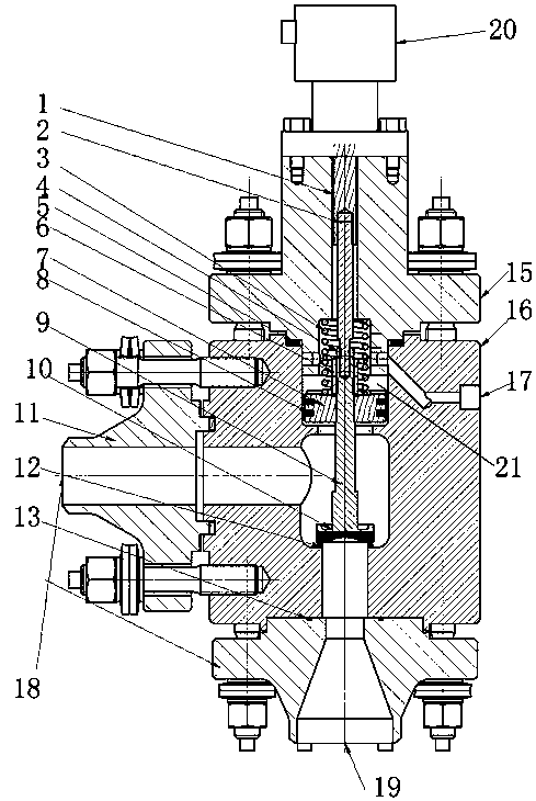
[0040] Such as figure 2 As shown, the structural diagram of the main valve of the present invention, on the basis of Embodiment 1, the main valve 22 includes an upper head 15 and a valve body 16, and the top of the upper head 15 is provided with a position indicator 20; the bottom of the upper end 15 Set on the upper end of the valve body 16, the inside of the upper head 15 is provided with a position sensing block 1 and a connecting rod 2 sequentially from top to bottom, and the sensing block 1 is connected to the connecting rod 2; the inside of the valve body 16 is arranged sequentially from top to bottom There are return spring 3, valve stem 9, piston assembly, valve disc 10 and valve seat 12, the valve stem 9 is connected with the connecting rod 2, the piston assembly is arranged on the valve stem 9, the bottom of the valve stem 9 is provided with a valve disc, the valve The valve seat 12 is closely attached to the valve seat 12. The valve seat 12 can be directly welded t...


PUM


Abstract

The invention discloses a pilot-operated safety valve system, which comprises a main valve, a pilot valve and a release valve. The main valve is provided with a main valve inlet, a main valve outlet and a flow channel hole. The pilot valve is provided with an upper end sensor The inlet of the pressure chamber, the discharge hole, the inlet of the relay valve and the outlet of the relay valve. The inlet of the main valve communicates with the inlet of the upper pressure-sensing chamber of the pilot valve through the pipeline and the isolation valve. The inlet of the relay valve of the valve is connected, and the outlet of the main valve of the main valve is respectively connected with the discharge hole of the pilot valve and the outlet of the relay valve through the pipeline and the isolation valve. The main valve, pilot valve, relay valve and relief valve in the pilot-operated safety valve system all adopt pressure self-tightening sealing structure, that is, the medium pressure acts on the periphery of the disc, the greater the system pressure, the greater the sealing force, so the sealing Reliable performance. Two to three pilot valves can be arranged on the main valve body, and different set pressures can be set respectively to realize redundant design, which improves the reliability of the automatic overpressure protection function of the safety valve.

Description

technical field [0001] The invention relates to the field of valve control in nuclear power generation, in particular to a pilot safety valve system, in particular to an overpressure protection device suitable for the primary circuit system of a pressurized water reactor nuclear power plant. Background technique [0002] Safety valves are installed on fluid pressure systems such as equipment, containers or pipelines. When the pressure in the system rises and exceeds the setting value of the safety valve, the safety valve can be automatically opened under the action of its own pressure medium, and then fully discharged to prevent the system from continuing to increase; when the pressure drops to the specified reseating pressure, The valves must also be able to close automatically and in a timely manner so that the system continues to operate safely. [0003] The nuclear safety safety valve used in the primary circuit system of nuclear reactor is the key equipment to ensure t...

Claims


Application Information

Patent Timeline
Patent Type & Authority Patents(China)
IPC IPC(8): F16K17/10F16K1/48F16K1/42F16K25/00F16K37/00
CPCF16K1/42F16K1/48F16K17/10F16K25/005F16K37/00
Inventor 郭松王宇翔李晓钟杨勇
Owner NUCLEAR POWER INSTITUTE OF CHINA
Why Eureka
Try Eureka