Comprehensive smoke purification technical method

A flue gas and incineration flue gas technology, applied in the field of environmental energy, can solve the problems of poor removal of harmful substances and unreasonable flue gas treatment process.

Inactive Publication Date: 2017-02-15
深圳市粤昆仑环保实业有限公司
View PDF8 Cites 3 Cited by
  • Summary
  • Abstract
  • Description
  • Claims
  • Application Information

AI Technical Summary

Problems solved by technology

[0005] The flue gas treatment process for waste incineration provided by the present invention aims to overcome the disadvantages of the unreasonable flue gas treatment process for waste incineration in the prior art, resulting in poor removal effect of harmful substances in the flue gas

Method used


Image

  • Comprehensive smoke purification technical method

Examples


Embodiment Construction

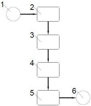
[0014] After municipal solid waste enters the pyrolysis combustion device, the flue gas 1 produced after a series of processes such as drying, pyrolysis, and oxidative decomposition enters the pyrolysis chamber through the return pipe for high-temperature flue gas utilization 2 as a heat source for waste pyrolysis Supplement, reduce energy consumption in the pyrolysis process; then discharge into the garbage drying room for flue gas cooling and reuse 3, make full use of the heat energy in the flue gas to dry the garbage, reduce the moisture content, and at the same time achieve the effect of flue gas cooling Purpose: The flue gas after cooling is discharged from the garbage pyrolysis combustion device, and enters the alkali washing tank for alkali washing of the flue gas 4 to remove acid gas and dust in the flue gas; the flue gas after alkali washing is dehydrated for flue gas drying 5 , to remove the water vapor mixed in the flue gas; after the dried flue gas is tested to meet...


PUM


Abstract

The invention provides a smoke treatment process used for garbage incineration. The smoke treatment process aims at overcoming the defect that a smoke treatment process used for garbage incineration in the prior art is not reasonable, and consequently the removing effect on harmful substances in smoke is poor. The invention aims at providing a technical method for treating incineration smoke, and the method can be used for effectively conducting stabilized treatment on incineration smoke with complex composition variation.

Description

technical field [0001] The invention relates to the field of environmental energy, in particular, the invention relates to a process for treating incineration flue gas. Background technique [0002] Garbage incineration is an effective way to realize the harmlessness, reduction, and recycling of garbage, but it will inevitably produce toxic and harmful gases such as sulfur dioxide, dioxin, and heavy metals, among which dioxin is a strong carcinogen. The danger of heavy metals is that they cannot be decomposed by microorganisms and can be enriched in organisms, and eventually cause harm to the human body through the food chain, leading to cancer and various diseases; and heavy metals can also pollute soil, water and the atmosphere, causing serious damage to the environment. [0003] In the prior art, activated carbon is often used to treat the flue gas produced by waste incineration. Activated carbon is an adsorbent that contains a large number of micropores and has a large s...

Claims


Application Information

Patent Timeline
Patent Type & Authority Applications(China)
IPC IPC(8): F23G5/027F23G5/04F23G5/44F23G5/46F23J15/00F23J15/02F23J15/06
CPCF23G5/027F23G5/04F23G5/44F23G5/46F23J15/00F23J15/02F23J15/06
Inventor 马随涛周亮夏观强雷福星谭美玲甘林颜德兴林珊虹
Owner 深圳市粤昆仑环保实业有限公司
Why Eureka
Try Eureka