Cracking Furnace Tube In-Situ Coating Processing Heat Treatment Furnace

A technology for cracking furnace tubes and heat treatment furnaces, which is applied in the field of furnace tube heating, and can solve problems such as difficult to strictly control the heating and cooling speed, poor heat preservation effect, and repeated construction, so as to shorten the heat treatment time, save hydrogen gas, and improve labor efficiency. Effect

Active Publication Date: 2019-01-18
CHINA PETROLEUM & CHEM CORP +2
View PDF9 Cites 0 Cited by
  • Summary
  • Abstract
  • Description
  • Claims
  • Application Information

AI Technical Summary

Problems solved by technology

[0006] 1. The heat treatment furnace is a one-time temporary installation. It will be dismantled after the heat treatment is completed, and repeated construction is required for the second treatment.
[0007] 2. Due to the temporary setting, the insulation effect is poor
It is difficult to strictly control the heating and cooling speed
[0008] 3. Temporary connection between pipes is required, and it needs to be cut off and re-polished after heat treatment, which is time-consuming and labor-intensive
low efficacy

Method used


Image

  • Cracking Furnace Tube In-Situ Coating Processing Heat Treatment Furnace
  • Cracking Furnace Tube In-Situ Coating Processing Heat Treatment Furnace
  • Cracking Furnace Tube In-Situ Coating Processing Heat Treatment Furnace

Examples


Embodiment Construction

[0038] The present invention will be further described below in conjunction with the drawings:

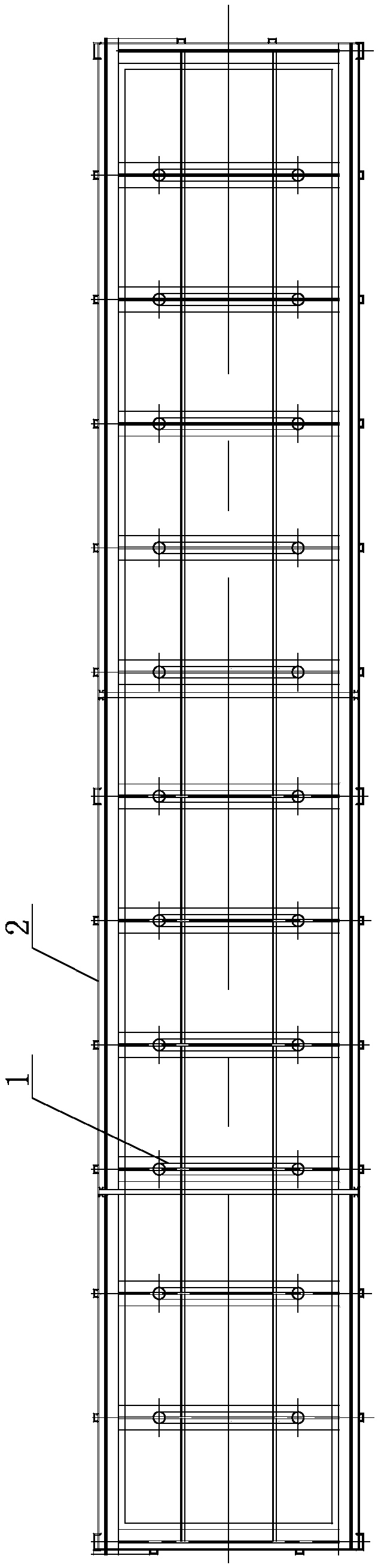
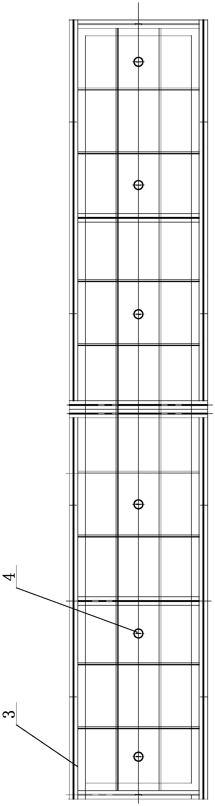
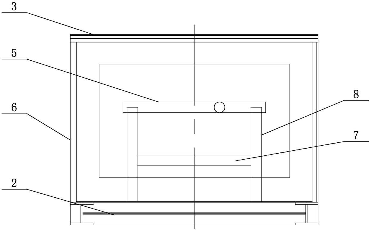
[0039] Such as Figure 1 ~ Figure 6 As shown, the heat treatment furnace for in-situ coating processing of cracking furnace tubes of the present invention includes a furnace cavity formed by a bottom frame 2, a wall plate 6 and a top cover plate 3. The gantry 1 is distributed in the furnace cavity, and the gantry 1 is installed On the underframe 2, there are two layers of beams on the gantry 1, which are the upper beam 5 and the lower beam 7, respectively. The upper beam 5 and the lower beam 7 are both installed on the column 8, and the column 8 is fixed on the underframe 2. A bottom electric heating plate is arranged between the gantry 1, and the bottom electric heating plate is fixed on the bottom frame 2. The outer circumference of the bottom frame 2 is a wall plate 6, and the top cover plate 3 is set on the top of the wall plate 6, and the front and rear side walls Fire holes 4 a...


PUM

PropertyMeasurementUnit
thicknessaaaaaaaaaa

Abstract

The invention is mainly applied to the technical field of furnace pipe heating, and in particular, relates to a cracking furnace pipe in-situ coating treatment heat treatment furnace. The cracking furnace pipe in-situ coating treatment heat treatment furnace comprises a bottom frame, wall plates and a top cover plate to form a furnace cavity; portal frames are distributed in the furnace cavity; the portal frames are mounted on the bottom frame; two layers of cross beams are arranged on the portal frames; bottom electric heating chips are arranged between the adjacent portal frames, and are fixed on the bottom frame; the periphery of the bottom frame is the wall plates; the top cover plate is arranged at the tops of the wall plates; the wall plates on the front and back two sides and the top cover plate are provided with fire observing holes; staff access ports and process pipe outlets are respectively formed in the wall plates at the left and right two ends; and thermocouples, electric wire sleeves and side electric heating chips are respectively arranged on the inner sides of the wall plates on the front and back two sides. The cracking furnace pipe in-situ coating treatment heat treatment furnace can be used for heat treatment of pressure containers, can perform the heat treatment for equipment with different lengths and specifications through such forms as adding of separation plates and heightening, and can achieve multiple purposes.

Description

Technical field [0001] The invention relates to a heat treatment furnace for in-situ coating processing of cracking furnace tubes, which is mainly applied to the technical field of furnace tube heating. Background technique [0002] The in-situ coating processing technology of the cracking furnace tube is a patented technology developed by the Beijing Research Institute of Chemical Industry. The coating component comes from the furnace tube substrate itself. The coating and the substrate are firmly bonded and have excellent anti-coking and anti-carburization properties. The in-situ coating can inhibit the coking of the cracking furnace tube of the ethylene device and prolong the effective production time of the device. Reduce energy consumption, increase the service life of furnace tubes, and improve the economic benefits of ethylene plants. The BA1102 cracking furnace of Sinopec Yanshan Branch applied the in-situ coating suppression technology of Beijing Research Institute of C...

Claims


Application Information

Patent Timeline
Patent Type & Authority Patents(China)
IPC IPC(8): F27B17/00F27D11/00F27D1/04
CPCF27B17/00F27D1/04F27D11/00
Inventor 王朝岭司广标梁文生刘靖涛
Owner CHINA PETROLEUM & CHEM CORP
Why Eureka
Try Eureka