One-dimensional temperature field modulation method

A modulation method and temperature field technology, applied in nonlinear optics, instruments, optics, etc., to achieve the effects of easy integration, low cost, and small volume

Active Publication Date: 2017-02-15
蚌埠正浩电子科技有限公司
View PDF3 Cites 6 Cited by
  • Summary
  • Abstract
  • Description
  • Claims
  • Application Information

AI Technical Summary

Problems solved by technology

This is not possible with traditional planar heaters

Method used


Image

  • One-dimensional temperature field modulation method
  • One-dimensional temperature field modulation method
  • One-dimensional temperature field modulation method

Examples


Embodiment Construction

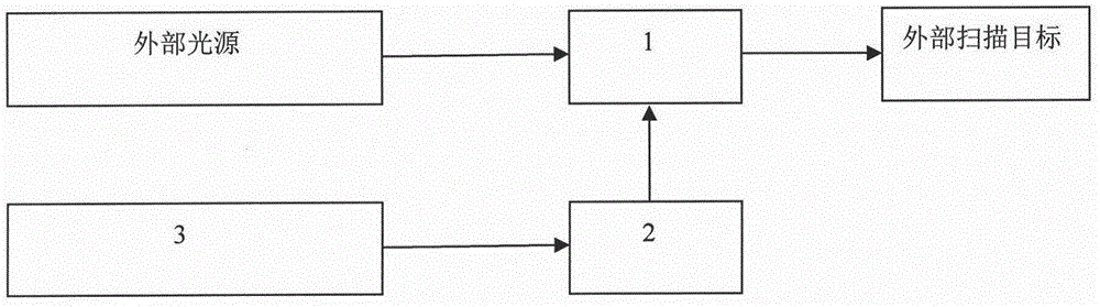
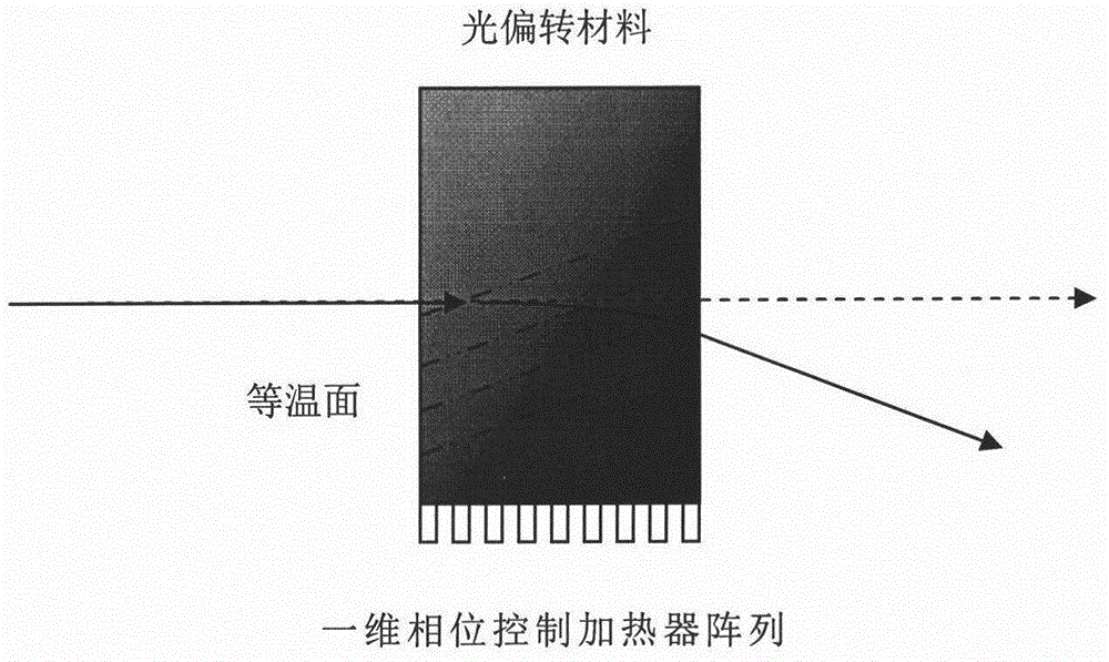
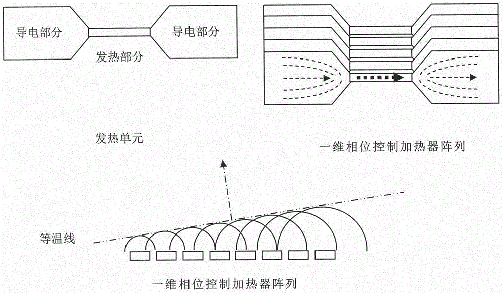
[0026] Below in conjunction with accompanying drawing and embodiment the present invention will be further described: as figure 1 and figure 2 As shown, it includes the following steps:

[0027] 1) Calculate the drive signal phase difference between two adjacent heating units in the one-dimensional phase control heater array, the drive signal phase difference is based on the sandwich between the isothermal surface of the gradient temperature field and the heater array plane angle, the number and resistance value of heaters, the thermal conductivity of light deflection material and other parameters, the one-dimensional phase control heater array is formed by arranging a plurality of heating units along one-dimensional direction;

[0028] 2) Input the phase difference of the drive signal obtained in step 1) into the control circuit to generate multiple drive signals with a specific phase difference between two adjacent signals, and the control circuit is used to generate a hea...


PUM

PropertyMeasurementUnit
temperature coefficient of refractive indexaaaaaaaaaa
surface roughnessaaaaaaaaaa
thicknessaaaaaaaaaa

Abstract

The invention relates to a one-dimensional temperature field modulation method, in particular to a method for carrying out one-dimensional temperature field modulation by adopting a one-dimensional phase control heater array. The modulation method comprises the following steps of: 1) calculating driving signal phase difference between two adjacent heating units in the one-dimensional phase control heater array; 2) inputting the driving signal phase difference obtained in the step 1) into a control circuit to produce a multichannel driving signal with specific phase difference between two adjacent signals; and 3) transmitting the multichannel driving signal obtained in the step 2) to a corresponding heating unit in the one-dimensional phase control heater array, so as to produce an inclined gradient temperature field in a light deflection material, and a solid-state optical scanning device realizes light beam deflection and scanning.

Description

technical field [0001] The invention relates to a one-dimensional temperature field modulation method, in particular to a one-dimensional temperature field modulation method using a one-dimensional phased controlled heater array (Phased Heated Array). Background technique [0002] At present, optical scanners are widely used in occasions that require rapid deflection of light beams through optical elements to form one-dimensional, two-dimensional or three-dimensional graphics, such as barcode scanning, optical scanning microscopes, laser projection TVs, etc. The usual large-size optical scanners can be divided into electromagnetic mechanical deflection (such as galvanometer Galvanometer), polyhedral prism mechanical deflection, electro-optic deflection, acousto-optic deflection, etc. according to the core optical deflection components; for Microelectromechanical Systems (Microelectromechanical Systems) , MEMS) miniature optical scanners can be divided into electrothermal typ...

Claims


Application Information

Patent Timeline
Patent Type & Authority Applications(China)
IPC IPC(8): G02F1/29
CPCG02F1/29
Inventor 徐英舜刘淑静
Owner 蚌埠正浩电子科技有限公司
Why Eureka
Try Eureka