Infrared camera mechanical structure

An infrared camera and mechanical structure technology, applied in the infrared field, can solve the problems of high cost and high processing precision requirements, and achieve the effects of simple focusing method, reduced manufacturing cost and simple structure

Inactive Publication Date: 2017-02-15
CHANGCHUN INST OF OPTICS FINE MECHANICS & PHYSICS CHINESE ACAD OF SCI
View PDF3 Cites 1 Cited by
  • Summary
  • Abstract
  • Description
  • Claims
  • Application Information

AI Technical Summary

Problems solved by technology

[0004] In order to solve the problems of high processing accuracy and high cost caused by the use of cam focusing mechanisms and the use of cylindrical guides on the inner wall of the lens barrel for most infrared cameras, the present invention provides a mechanical structure for infrared cameras

Method used


Image

  • Infrared camera mechanical structure
  • Infrared camera mechanical structure
  • Infrared camera mechanical structure

Examples


Embodiment Construction

[0039] The present invention will be described in further detail below in conjunction with the accompanying drawings.

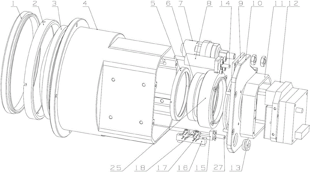
[0040] Such as Figure 1 to Figure 6 As shown, a mechanical structure of an infrared camera of the present invention mainly includes: a mirror cover 1, a pressure ring 1 2, a lens 3, a lens barrel 4, a pressure ring 2 5, a lens 2 6, a linear motor assembly 7, and a guide assembly 8 , Stress plate 9, rear cover 10, detector seat 11, detector 12, grommet 13, block mounting seat 15, photoelectric switch seat 16, two photoelectric switches 17, block plate 18, focusing lens seat 25 .

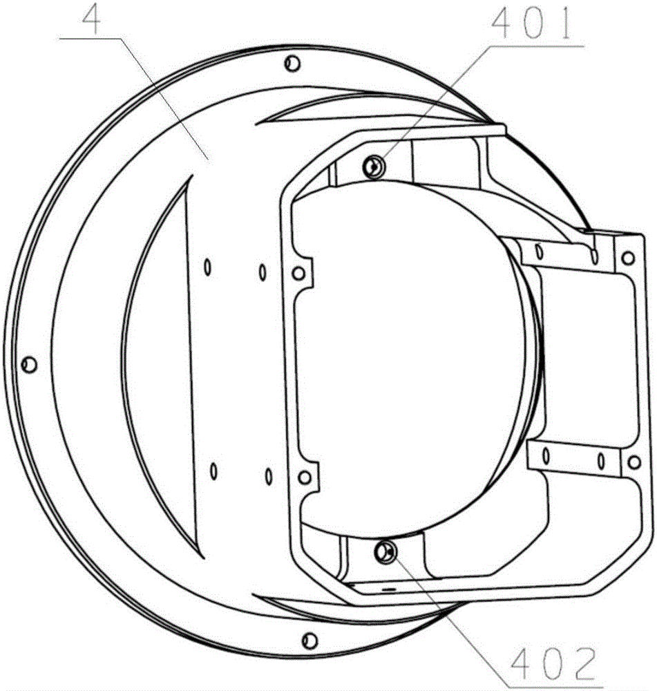
[0041] Such as figure 2 As shown, the front end of the lens barrel 4 is provided with a flange, and the rear end of the lens barrel 4 is provided with a mounting structure. The inner and lower sides of the structure are provided with three cylinder positioning holes 401 and four cylinder positioning holes 402 .

[0042] Lens one 3 is fixed on the lens barrel 4 by pressure ring ...


PUM


Abstract

The invention relates to an infrared camera mechanical structure, belongs to the infrared field, and solves the problems of high processing precision requirement and high cost brought by adoption of a cam focusing mechanism and lens barrel inner wall cylinder guiding by most infrared cameras. The infrared camera mechanical structure includes a lens cover, a pressing ring I, a lens I, a lens barrel, a pressing ring II, a lens II, a linear motor assembly, a guiding assembly, a force bearing plate, a rear cover, a detector seat, a detector, a wire protecting cover, a separation blade installation seat, a photoelectric switch seat, two photoelectric switches, a separation blade and a focusing lens seat. The linear motor assembly provides power drive for linear motion required by focusing of the infrared camera. The guiding assembly provides necessary linear guiding for linear motion required by focusing of the infrared camera. The infrared camera mechanical structure provided by the invention adopts a miniature linear motor to directly drive an axis linear drive mode of a focusing lens and adopts a linear motion pair formed by a guiding shaft and a linear bearing to complete focusing motion required by the infrared camera, completely gets rid of a traditional cam drive mode, and the manufacturing cost of the camera is substantially reduced.

Description

technical field [0001] The invention belongs to the field of infrared technology, and in particular relates to a mechanical structure of an infrared camera. Background technique [0002] Infrared technology is more and more applied to people's daily life, such as security monitoring, forest fire prevention, temperature monitoring, etc. Therefore, the use of infrared cameras is becoming more and more common, but traditional infrared cameras are Factors such as mechanical structure limitations and dependence on imported detectors make the cost of traditional infrared cameras high, which limits the application of infrared cameras. Most of them are in the military field, but rarely in the civilian field. If you want to further expand the application range of infrared cameras, you must reduce its production costs from all aspects. [0003] At present, most infrared cameras use a cam focusing mechanism. The processing of the cam focusing mechanism requires high precision, and the...

Claims


Application Information

Patent Timeline
IPC IPC(8): G03B13/34G02B7/04
CPCG02B7/04G03B13/34
Inventor 黄剑波王健刘建卓孙强
Owner CHANGCHUN INST OF OPTICS FINE MECHANICS & PHYSICS CHINESE ACAD OF SCI
Why Eureka
Try Eureka