Actuating structure of electrical connector

A technology for actuating structures and electrical connectors, which is applied to conductive connections, connections, and components of connecting devices, etc., can solve the problem of reducing the size and height of connectors, increasing the overall height and complexity of structural design, and difficulty in joining and fixing. and other problems, to achieve the effect of firm clamping, simple structure and easy operation

Inactive Publication Date: 2017-02-15
TARNG YU ENTERPRISE
View PDF5 Cites 1 Cited by
  • Summary
  • Abstract
  • Description
  • Claims
  • Application Information

AI Technical Summary

Problems solved by technology

[0002] By the way, today's computer and electronic technology is developing rapidly, and various electronic products have been popularized in every corner of society; Fast and light, thin, short, and small, the size and height of the connector inside the product need to be greatly reduced. In response to this development trend, the lower circuit board or motherboard is connected to the two Connectors between wires are bound to be more difficult to join and fix
[0003] However, the connectors connected between the two wires are directly welded or locked on the circuit board or the main board, and the connectors connected between the two wires are generally made of insulating bases and clamping terminals made of conductive metal materials. and the button for actuation. When the wire or terminal is inserted into the insulating base and the clamping opening of the clamping terminal, so that the clamping terminal presents an electrical connection of elastic clamping, it can be pressed down by means of the button above the insulating base. Pushing in a biased way opens the opening of the clamping terminal, and then pulls the wire or terminal out from the inside of the insulating seat and the clamping terminal to the outside, so as to achiev

Method used


Image

  • Actuating structure of electrical connector
  • Actuating structure of electrical connector
  • Actuating structure of electrical connector

Examples


Embodiment Construction

[0033] In order to achieve the above-mentioned purpose and effect, the technical means adopted in the present invention, its structure, and the method of implementation, etc., are hereby described in detail with respect to the preferred embodiments of the present invention. Its features and functions are as follows, so that it can be fully understood.

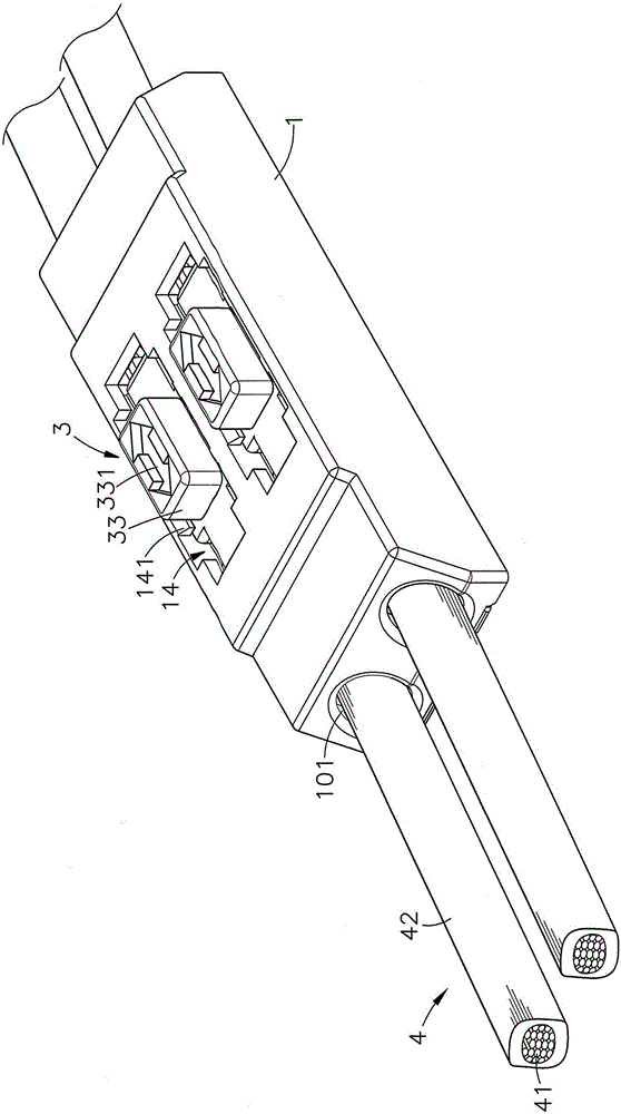
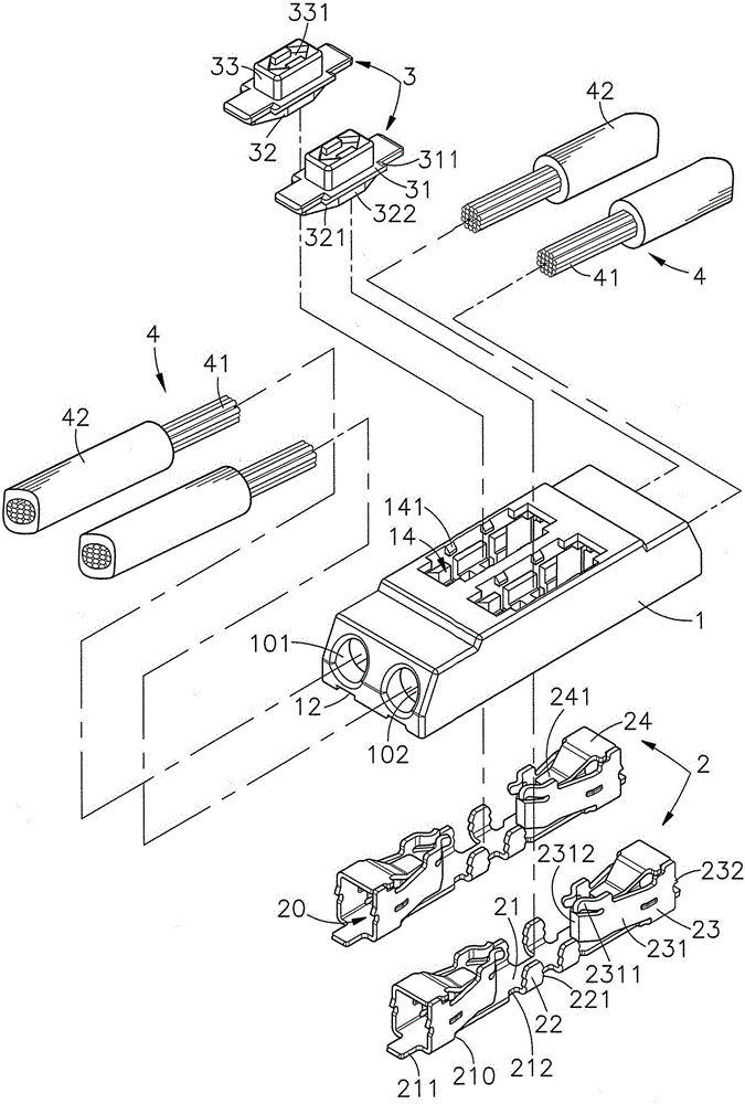
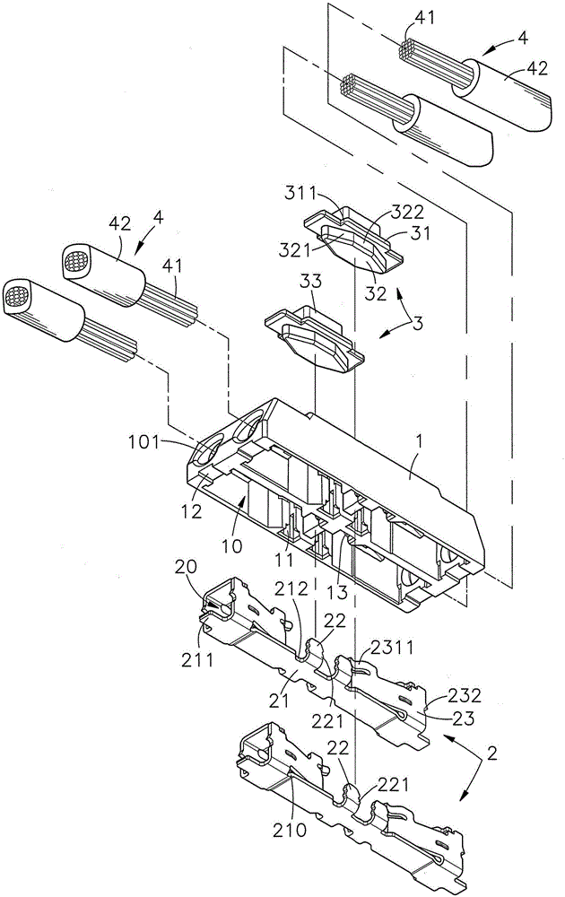
[0034] see figure 1 , figure 2 , image 3 , Figure 4 As shown, it is a three-dimensional appearance view, a three-dimensional exploded view, a three-dimensional exploded view of another angle, and a side sectional view of a preferred embodiment of the present invention. It can be clearly seen from the figure that the present invention includes a seat body 1, Clamping terminal 2 and pushing block 3, wherein:

[0035] The hollow of the base body 1 is respectively provided with two sets of two accommodating spaces 10 with openings 101 at the front and rear, and the central upper surface of the base body 1 is provided with a h...


PUM


Abstract

The invention relates to an actuating structure of an electric connector, which comprises a base, a holding terminal positioned in a receiving room of the seat, and a shifting block slidably positioned at a center horizontal shifting room of the seat. The front and rear sides of the seat are provided with openings. A base portion of the holding terminal is provided with a penetrating passage, side plates with both front and rear sides bent, and suspending elastic arms relatively inwards obliquely extending from the rear sides of the side plates. Shifting surfaces are arranged at front and rear sides of the shifting block, a first position of each shifting surface is located outside a gap between the two suspending elastic arms of the holding terminal, such that the two suspending elastic arms may be held on the outer diameter of the center conductor of the cable. When a top-push block is moved towards a direction different form a holding direction of the cable, a second position of each shifting surface after horizontal displacement is located within the gap between the two suspending elastic arms of the holding terminal in a movement direction, such that the two elastic arms will be elastically deformed outwardly to insert or remove the center conductor of the cable in or from the opening, lest the outer diameter of the center conductor of the cable in the same direction is held or loosened in an operation manner of a tool.

Description

technical field [0001] The invention relates to an actuating structure of an electrical connector, especially a connector connected between two wires, which can easily clamp or loosen the outer diameter of the central conductor of the wires in the same direction in a tool-free operation. Background technique [0002] By the way, today's computer and electronic technology is developing rapidly, and various electronic products have been popularized in every corner of society; Fast and light, thin, short, and small, the size and height of the connector inside the product need to be greatly reduced. In response to this development trend, the lower circuit board or motherboard is connected to the two Connectors between wires are bound to be more difficult to join and fix. [0003] However, the connectors connected between the two wires are directly welded or locked on the circuit board or the main board, and the connectors connected between the two wires are generally made of in...

Claims


Application Information

Patent Timeline
IPC IPC(8): H01R13/629H01R13/639
CPCH01R13/629H01R13/639H01R12/515H01R4/48365
Inventor 陈宗錡黄睦容
Owner TARNG YU ENTERPRISE
Why Eureka
Try Eureka