No-position permanent magnet brushless direct current motor control device and control method thereof
A permanent magnet brushless DC and control device technology, which is applied in electronic commutation motor control, control systems, electrical components, etc., can solve problems such as hindering the promotion and use of brushless DC motors, hindering the development of motor equipment, and high cost. To achieve the effect of being conducive to promotion and use, low production cost and simple structure
- Summary
- Abstract
- Description
- Claims
- Application Information
AI Technical Summary
Problems solved by technology
Method used
Image

Examples
Embodiment Construction
[0036] In order to make the object, technical solution and advantages of the present invention more clear, the present invention will be further described in detail below in conjunction with the accompanying drawings and embodiments. It should be understood that the specific embodiments described here are only used to explain the present invention, not to limit the present invention.
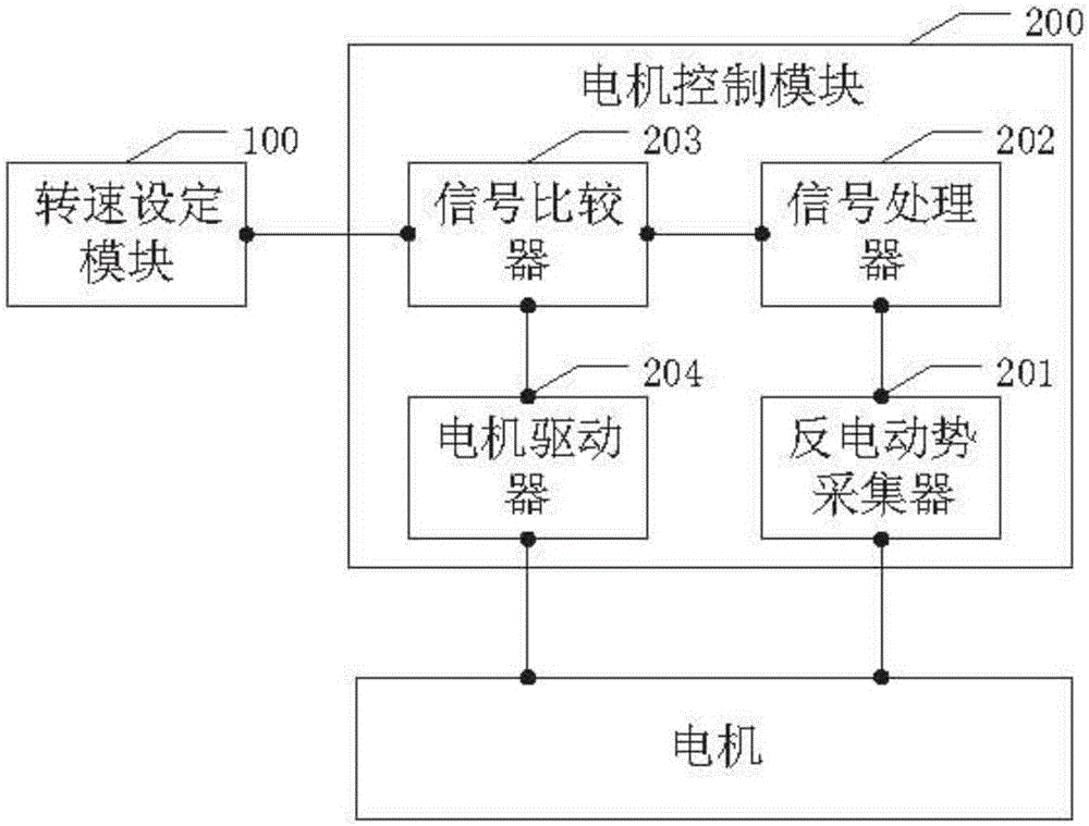
[0037] see Figure 1 to Figure 4 , the present invention is a control device for a positionless permanent magnet brushless DC motor, which cooperates with the motor and includes: a speed setting module 100 and a motor control module 200 connected to each other;
[0038] The speed setting module 100 is used to set the predetermined speed data of the motor;
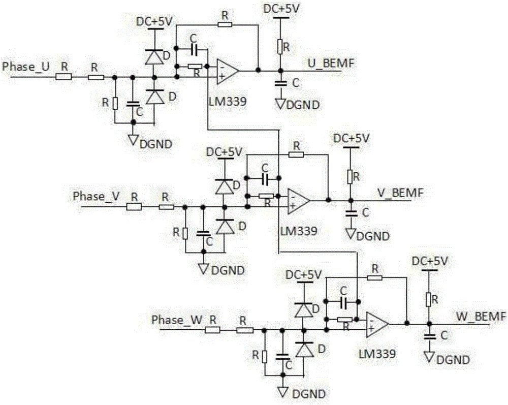
[0039] The motor control module 200 is connected to the three phase lines of the motor, and includes: a counter electromotive force collector 201, a signal processor 202, a signal comparator 203 and a motor driver 204;
[0040] The counter ...
PUM
 Abstract
Description
Claims
Application Information
 - Generate Ideas
- Intellectual Property
- Life Sciences
- Materials
- Tech Scout
- Unparalleled Data Quality
- Higher Quality Content
- 60% Fewer Hallucinations
Browse by: Latest US Patents, China's latest patents, Technical Efficacy Thesaurus, Application Domain, Technology Topic, Popular Technical Reports.
© 2025 PatSnap. All rights reserved.Legal|Privacy policy|Modern Slavery Act Transparency Statement|Sitemap|About US| Contact US: help@patsnap.com