Signal estimation method in non-reconstruction framework
A signal estimation and framework technology, applied in channel estimation, baseband systems, digital transmission systems, etc., and can solve problems such as slow reconstruction speed and poor accuracy
- Summary
- Abstract
- Description
- Claims
- Application Information
AI Technical Summary
Problems solved by technology
Method used
Image
Examples
specific Embodiment approach 1
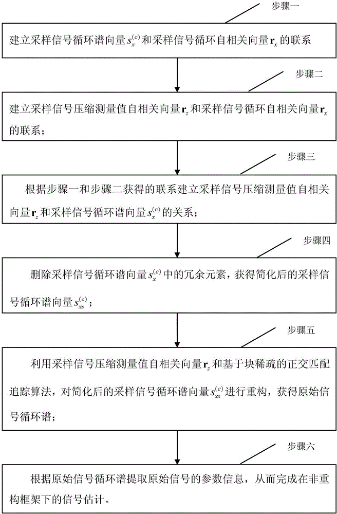
[0074] Specific implementation mode one: see figure 1 Describe this implementation mode, a signal estimation method under a non-reconfiguration framework described in this implementation mode, the method includes the following steps:
[0075] Step 1: Establish the cyclic spectrum vector of the sampled signal and sampled signal circular autocorrelation vector r x contact;
[0076] Step 2: Establish the sampling signal compression measurement value autocorrelation vector r z and sampled signal circular autocorrelation vector r x contact;
[0077] Step 3: According to the relationship obtained in Step 1 and Step 2, establish the autocorrelation vector r of the compressed measurement value of the sampled signal z and the sampled signal cyclic spectrum vector Relationship;
[0078] Step 4: Delete the cyclic spectrum vector of the sampled signal Redundant elements in , to obtain the simplified sampled signal cyclic spectrum vector
[0079] Step 5: Use the sampling sig...
specific Embodiment approach 2
[0087] Specific embodiment 2: The difference between this embodiment and the signal estimation method under the non-reconstruction framework described in the specific embodiment 1 is that the cyclic spectrum vector of the sampled signal is established in the step 1 and sampled signal circular autocorrelation vector r x The specific steps of the contact are;
[0088] Step 11: Establish the sampled signal autocorrelation matrix R according to the sampled signal x ,in,
[0089]
[0090] Sampled signal autocorrelation matrix R x Satisfy n+vx After de-redundancy, it is converted into a vector form to obtain the sampled signal circular autocorrelation vector r x ,and
[0091]
[0092] in, express yes Find the mean, E{} means find the mean, x t represents the sampled signal, Indicates the transpose of the sampled signal, r x Indicates the sampling signal autocorrelation vector, r x (n, ν) represents the autocorrelation value with index (n, ν), n represents the time,...
specific Embodiment approach 3
[0113] Specific Embodiment 3: The difference between this embodiment and the signal estimation method under the non-reconfiguration framework described in Specific Embodiment 2 is that in the step 2, the autocorrelation vector r of the compressed measurement value of the sampled signal is established. z and sampled signal circular autocorrelation vector r x The specific steps for contacting are:
[0114] Step 21: First, compress the sampled signal to obtain the compressed measurement value z t , then for the original signal x t and the compression measure z t Perform an autocorrelation operation to obtain the sampled signal autocorrelation matrix R x and sampled signal compression measurement value autocorrelation matrix R z , where z t =Ax t ,
[0115] Define the sampling signal autocorrelation matrix R x The circular autocorrelation vector r with the sampled signal x The mapping relationship between them is:
[0116] vec{R x}=PNr x (formula ten),
[0117] Defin...
PUM
 Abstract
Description
Claims
Application Information
 - R&D
- Intellectual Property
- Life Sciences
- Materials
- Tech Scout
- Unparalleled Data Quality
- Higher Quality Content
- 60% Fewer Hallucinations
Browse by: Latest US Patents, China's latest patents, Technical Efficacy Thesaurus, Application Domain, Technology Topic, Popular Technical Reports.
© 2025 PatSnap. All rights reserved.Legal|Privacy policy|Modern Slavery Act Transparency Statement|Sitemap|About US| Contact US: help@patsnap.com


