Automatic focusing method and system based on RGB-IR depth camera

A technology of auto-focus and depth camera, which is applied to TV system parts, color TV parts, TV, etc. It can solve the problems of large amount of calculation and cannot auto-focus, achieve fast auto-focus, increase speed, and reduce calculation amount Effect

Active Publication Date: 2017-02-15
SHENZHEN ORBBEC CO LTD
View PDF4 Cites 39 Cited by
  • Summary
  • Abstract
  • Description
  • Claims
  • Application Information

AI Technical Summary

Problems solved by technology

[0007] The purpose of the present invention is to propose an auto-focus method and system based on a depth camera to solve the technical problems in the above-mentioned prior art that the amount of calculation is large and the auto-focus cannot be performed smoothly due to improper acquisition of depth information

Method used


Image

  • Automatic focusing method and system based on RGB-IR depth camera
  • Automatic focusing method and system based on RGB-IR depth camera
  • Automatic focusing method and system based on RGB-IR depth camera

Examples


Embodiment 1

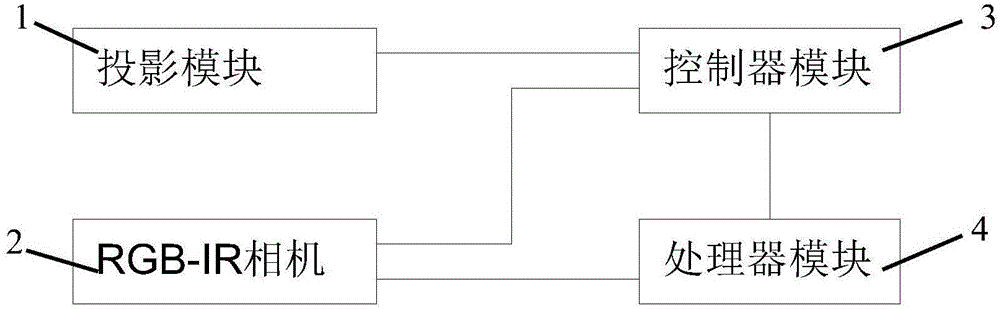
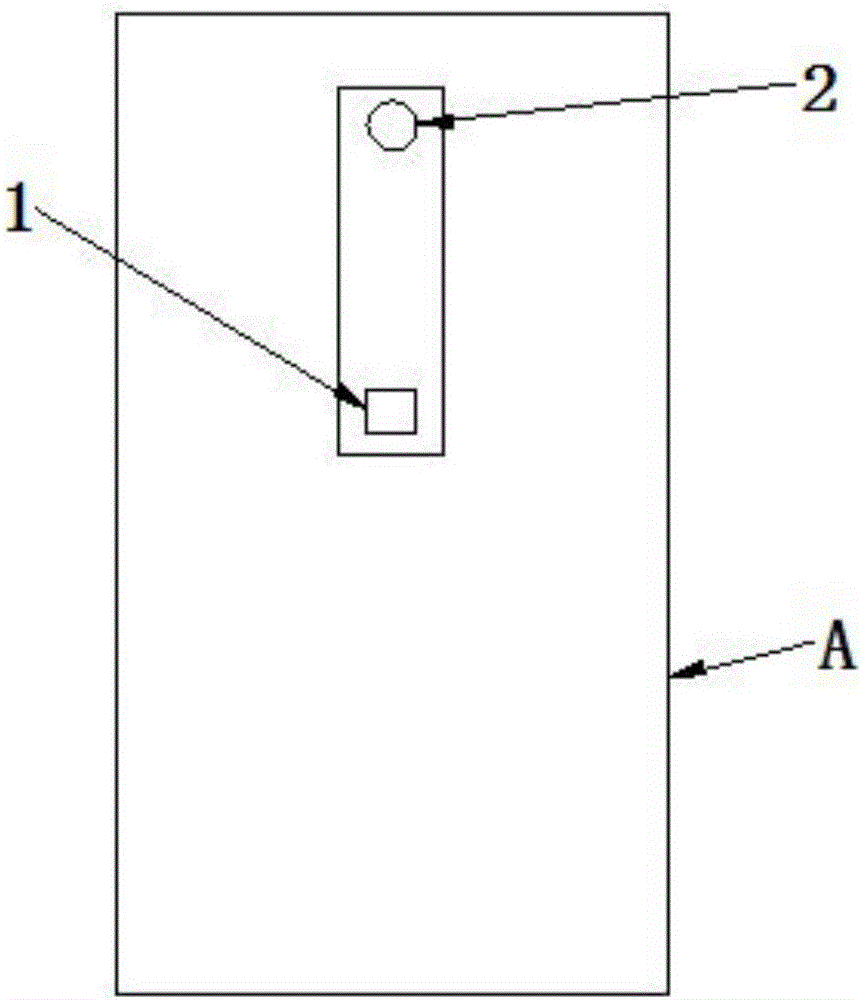
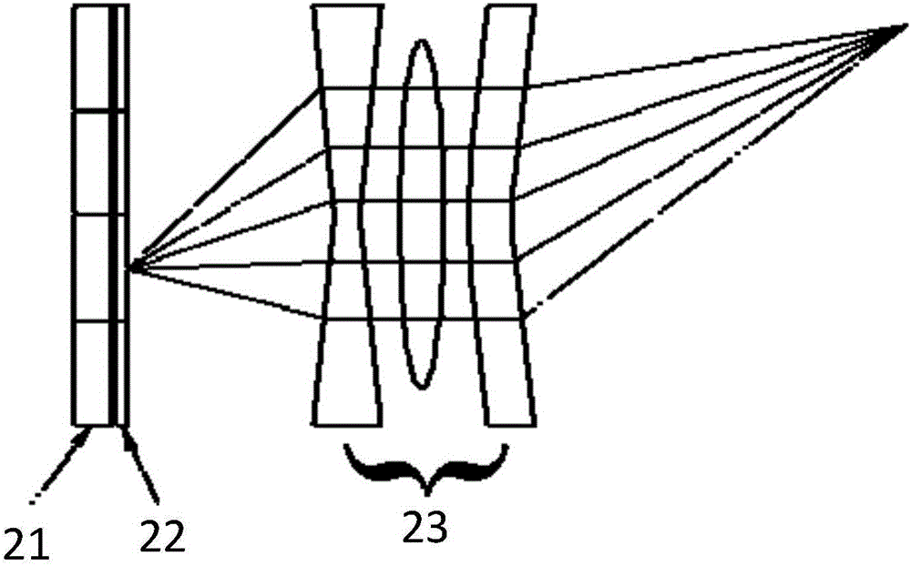
[0043] This embodiment proposes an autofocus system based on an RGB-IR depth camera, and the RGB-IR camera can simultaneously acquire visible light (RGB image) data and infrared light data. like figure 1 As shown, the projection module 1, the RGB-IR camera 2, the processor module 4 and the controller module 3, the projection module 1 is used to project the encoded infrared structured light pattern to the target space; the RGB-IR camera 2 is used to acquire the focus synchronously The structured light infrared image of area 5 and the RGB image of the target area, the depth camera unit and the zoom camera unit respectively obtain the depth image and the RGB image of the focus area 5; the processor unit is used to obtain the focus area 5 and the focus area in the RGB image 5 depth information; the controller module 3 is used to automatically focus the RGB-IR camera 2 according to the depth information; as image 3 As shown, the RGB-IR camera 2 includes an image sensor 21, a filt...

Embodiment 2

[0053] In this example, if Image 6 As shown, according to the autofocus system based on the RGB-IR depth camera proposed in Embodiment 1, an autofocus method based on the RGB-IR depth camera is proposed. This embodiment is mainly used for single-point focusing, and can refer to the optical path Figure 8 .

[0054] Firstly, S1, using the projection module 1 to project the coded infrared structured light pattern to the target space;

[0055] The projection module 1 has different structures according to different projection structures. This embodiment uses speckle granular structured light as an example for illustration. The projection module 1 generally consists of an infrared light source, a collimator lens and a diffractive optical element (DOE). The light source is an infrared laser, which can be a single edge emitting laser light source or a vertical cavity surface emitting laser array light source. Since the light emitted by the laser light source has a certain diverg...

Embodiment 3

[0069] In this example, if Figure 7 As shown, according to the auto-focus system based on the depth camera proposed in the first embodiment, an auto-focus method based on the RGB-IR depth camera is proposed. The difference between this embodiment and the second embodiment is that this embodiment is mainly for multi-point focus.

[0070] Firstly, S1, using the projection module 1 to project the coded infrared structured light pattern to the target space;

[0071] The projection module 1 has different structures according to different projection structures. This embodiment uses speckle granular structured light as an example for illustration. The projection module 1 generally consists of an infrared light source, a collimator lens and a diffractive optical element (DOE). The light source is an infrared laser, which can be a single edge emitting laser light source or a vertical cavity surface emitting laser array light source. Since the light emitted by the laser light sourc...


PUM


Abstract

The invention relates to the field of automatic focusing, in particular to a method for realizing automatic focusing by acquiring depth information through an RGB-IP depth camera and a camera system. The method comprises the following steps: S1, projecting an encoded infrared structure light pattern to a target space by using a projection module; S2, acquiring an RGB image of a target area by using an RGB-IR camera; S3, acquiring a focusing area needing to be focused in the RGB image; S4, capturing a depth extraction area only including the focusing area at a corresponding position of the acquired image by the depth camera according to the focusing area, only acquiring a structure light infrared image of the depth extraction area by using the RGB-IR camera, and calculating depth information of the focusing area according to the depth extraction area; and S5, automatically focusing through the RGB-IR camera according to the depth information. Through adoption of the automatic focusing method and system, any position in the target space can be automatically focused rapidly at high accuracy.

Description

technical field [0001] The invention relates to the field of autofocus, in particular to a method and a camera system for acquiring depth information by using an RGB-IR depth camera to realize autofocus. Background technique [0002] Auto-focus technology is the key to achieve high-quality images captured by the camera. Auto-focus technology is mainly divided into passive auto-focus and active auto-focus. Passive autofocus uses the sharpness of the image formed by the focused object on the image plane to focus. Generally, it needs to iterate through algorithms such as mountain climbing or gradient descent, that is, to adjust the focal length again and again until the image is the clearest. , the advantage of this method is that it does not need to use other devices, and the disadvantage is that the focusing speed is relatively slow. Active autofocus is based on the depth value of the focused object from the lens to achieve focusing. The methods used to measure the depth of ...

Claims


Application Information

Patent Timeline
Patent Type & Authority Applications(China)
IPC IPC(8): H04N5/232
CPCH04N23/67
Inventor 黄源浩刘龙肖振中许星
Owner SHENZHEN ORBBEC CO LTD
Why Eureka
Try Eureka