Autofocus method and system based on rgb-ir depth camera
An auto-focus and depth camera technology, applied to TV system parts, color TV parts, TVs, etc., can solve the problems of large amount of calculation and cannot auto-focus, achieve fast auto-focus, reduce calculation amount, and increase speed Effect
- Summary
- Abstract
- Description
- Claims
- Application Information
AI Technical Summary
Problems solved by technology
Method used
Image
Examples
Embodiment 1
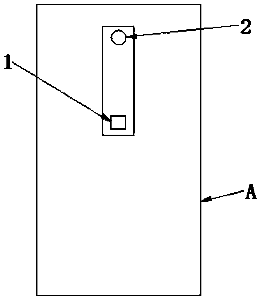
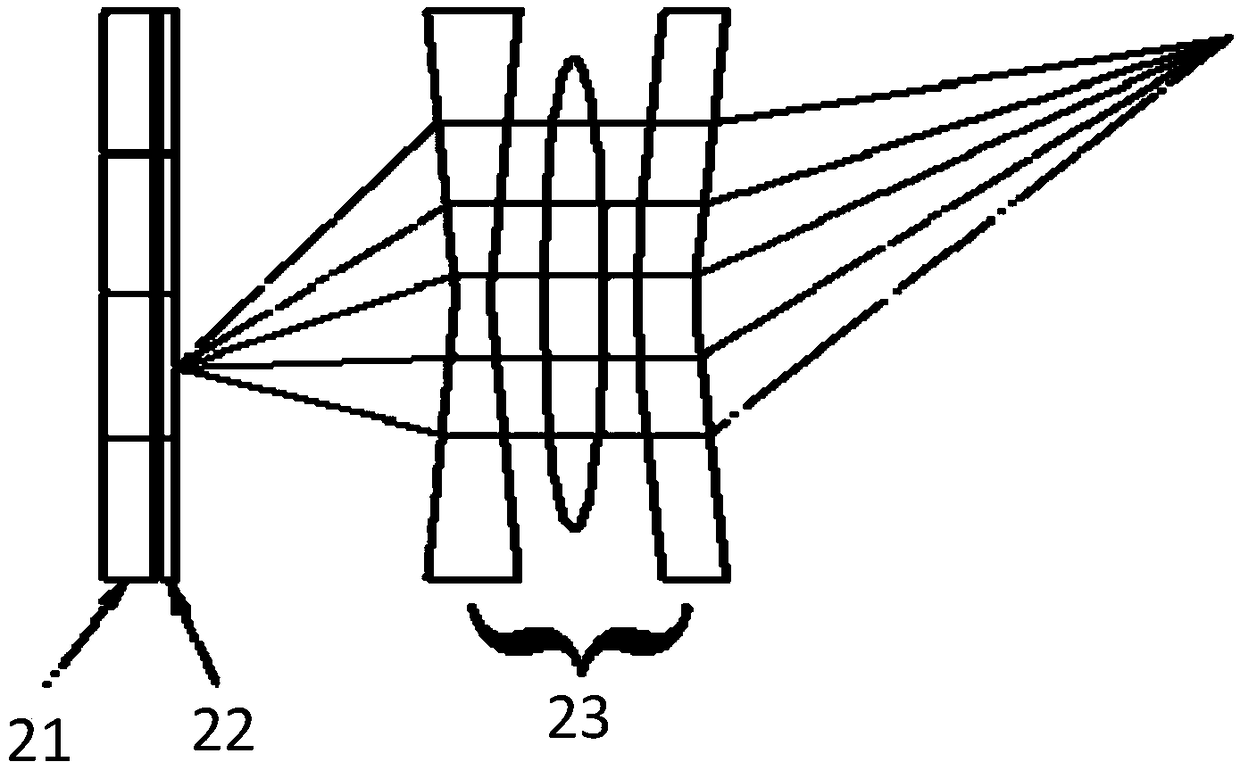
[0043] This embodiment proposes an autofocus system based on an RGB-IR depth camera, and the RGB-IR camera can simultaneously acquire visible light (RGB image) data and infrared light data. Such as figure 1 As shown, the projection module 1, the RGB-IR camera 2, the processor module 4 and the controller module 3, the projection module 1 is used to project the encoded infrared structured light pattern to the target space; the RGB-IR camera 2 is used to acquire the focus synchronously The structured light infrared image of area 5 and the RGB image of the target area, the depth camera unit and the zoom camera unit respectively obtain the depth image and the RGB image of the focus area 5; the processor unit is used to obtain the focus area 5 and the focus area in the RGB image 5 depth information; the controller module 3 is used to automatically focus the RGB-IR camera 2 according to the depth information; as image 3 As shown, the RGB-IR camera 2 includes an image sensor 21, a f...
Embodiment 2
[0053] In this example, if Image 6 As shown, according to the autofocus system based on the RGB-IR depth camera proposed in Embodiment 1, an autofocus method based on the RGB-IR depth camera is proposed. This embodiment is mainly used for single-point focusing, and can refer to the optical path Figure 8 .
[0054] Firstly, S1, using the projection module 1 to project the coded infrared structured light pattern to the target space;
[0055] The projection module 1 has different structures according to different projection structures. This embodiment uses speckle granular structured light as an example for illustration. The projection module 1 generally consists of an infrared light source, a collimator lens and a diffractive optical element (DOE). The light source is an infrared laser, which can be a single edge emitting laser light source or a vertical cavity surface emitting laser array light source. Since the light emitted by the laser light source has a certain diverg...
Embodiment 3
[0069] In this example, if Figure 7 As shown, according to the auto-focus system based on the depth camera proposed in the first embodiment, an auto-focus method based on the RGB-IR depth camera is proposed. The difference between this embodiment and the second embodiment is that this embodiment is mainly for multi-point focus.
[0070] Firstly, S1, using the projection module 1 to project the coded infrared structured light pattern to the target space;
[0071] The projection module 1 has different structures according to different projection structures. This embodiment uses speckle granular structured light as an example for illustration. The projection module 1 generally consists of an infrared light source, a collimator lens and a diffractive optical element (DOE). The light source is an infrared laser, which can be a single edge emitting laser light source or a vertical cavity surface emitting laser array light source. Since the light emitted by the laser light sourc...
PUM
 Abstract
Description
Claims
Application Information
 - R&D
- Intellectual Property
- Life Sciences
- Materials
- Tech Scout
- Unparalleled Data Quality
- Higher Quality Content
- 60% Fewer Hallucinations
Browse by: Latest US Patents, China's latest patents, Technical Efficacy Thesaurus, Application Domain, Technology Topic, Popular Technical Reports.
© 2025 PatSnap. All rights reserved.Legal|Privacy policy|Modern Slavery Act Transparency Statement|Sitemap|About US| Contact US: help@patsnap.com


