Filling system for operating fluid containers

A filling system, technology of working fluid, applied in the direction of machine/engine, arrangement in combination with fuel supply of internal combustion engine, exhaust gas treatment, etc., which can solve the problem of not being squeezed/cut or ripped from the fuel container or filling neck, etc., Achieving the effect of increased safety levels and low investment requirements

Active Publication Date: 2017-02-15
KAUTEX TEXTRON
View PDF4 Cites 2 Cited by
  • Summary
  • Abstract
  • Description
  • Claims
  • Application Information

AI Technical Summary

Problems solved by technology

However, these measures do not bring about the situation that, in the event of an accident and deformation of the receiving space in which the pipe system is accommodated in the vehicle, the pipe system itself is not crushed / cut or removed from the fuel container or filling neck ripped off

Method used


Image

  • Filling system for operating fluid containers
  • Filling system for operating fluid containers
  • Filling system for operating fluid containers

Examples


Embodiment Construction

[0049] In the description now following, the same reference numerals designate the same components or the same features, with the result that descriptions made with respect to components in one figure also apply to other figures, so that repeated descriptions are avoided.

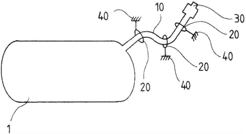
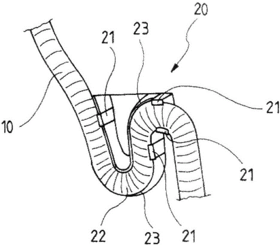
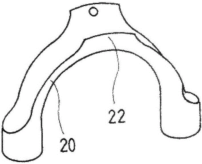
[0050] figure 1 A schematic diagram of a working fluid container 1 according to the invention and a filling system connected thereto according to the invention is shown. The working fluid container 1 is fluidically connected to a filling neck 30 via a filling hose 10 of the filling system. The filling hose 10 is fastened in the installation space of the motor vehicle by means of a plurality of filling hose holders 20 . In this case, a plurality of filling hose holders 20 are fixed at fastening points 40 in the installation space of the motor vehicle.

[0051] as from figure 1 It is obvious that since the filling hose 10 is fixed in the installation space of the motor vehicle by the filling hose holding d...


PUM


Abstract

The invention discloses a filling system for an operating fluid container (1) of a motor vehicle, comprising a filling hose (10) and at least one filling hose holding device (20). The filling hose holding device (20) can be fastened in an installation space of the motor vehicle, and the filling hose (10) can be fluid-connected to an operating fluid container (1) and to a filling neck (30). The filling hose (10) can be fastened in the installation space of the motor vehicle by means of the filling hose holding device (20) in such a manner that the filling hose (10) follows a contour defined by the filling hose holding device (20).

Description

technical field [0001] The invention relates to a filling system for a working fluid container of a motor vehicle. Furthermore, the invention relates to a working fluid container with a correspondingly designed filling system. Furthermore, the invention relates to a motor vehicle with a corresponding working fluid container. Background technique [0002] In the case of conventional working fluid containers, eg in the case of fuel containers, or in the case of SCR containers for holding aqueous urea solutions, the connection between the filling neck and the working fluid container is usually ensured by a rigid pipe connection. The rigid pipe connection can be formed, for example, by blow molding the part. In addition, the pipe connections can also be implemented by metal connections. [0003] In the case of a diesel motor vehicle and in the case of an SCR working fluid container, the pipe connection formed as a blow-molded part can be implemented in a single layer between ...

Claims


Application Information

Patent Timeline
Patent Type & Authority Applications(China)
IPC IPC(8): B60K15/01B60K15/04F16L3/12
CPCB60K15/01B60K15/04B60K2015/0464B60K2015/047B60K2015/0474F16L3/1226F01N2610/1413F01N3/2066F01N2610/02Y02A50/20F01N3/2896
Inventor D·欧利茨H·施西拉
Owner KAUTEX TEXTRON
Why Eureka
Try Eureka