Electropneumatic spring brake device of a motor vehicle with an abrupt pressure increase when releasing the brake

A technology for energy storage braking and motor vehicles, which is applied in the direction of braking transmission devices, braking action activation devices, hydraulic braking transmission devices, etc., and can solve problems such as unfavorable dynamics

Active Publication Date: 2017-02-15
KNORR-BREMSE SYST FUER NUTZFAHRZEUGE GMBH
View PDF7 Cites 6 Cited by
  • Summary
  • Abstract
  • Description
  • Claims
  • Application Information

AI Technical Summary

Problems solved by technology

[0007] However, it is problematic in such spring-loaded brake cylinders that in order to counteract the action of the stored-energy spring for brake release by filling the spring-charged brake chamber with air, certain frictional effects must first be overcome. Breakaway force until the spring-loaded brake piston can move into the brake release position, which can lead to unfavorable dynamics in the context of e.g. pressure-regulated auxiliary braking

Method used


Image

  • Electropneumatic spring brake device of a motor vehicle with an abrupt pressure increase when releasing the brake
  • Electropneumatic spring brake device of a motor vehicle with an abrupt pressure increase when releasing the brake
  • Electropneumatic spring brake device of a motor vehicle with an abrupt pressure increase when releasing the brake

Examples


Embodiment Construction

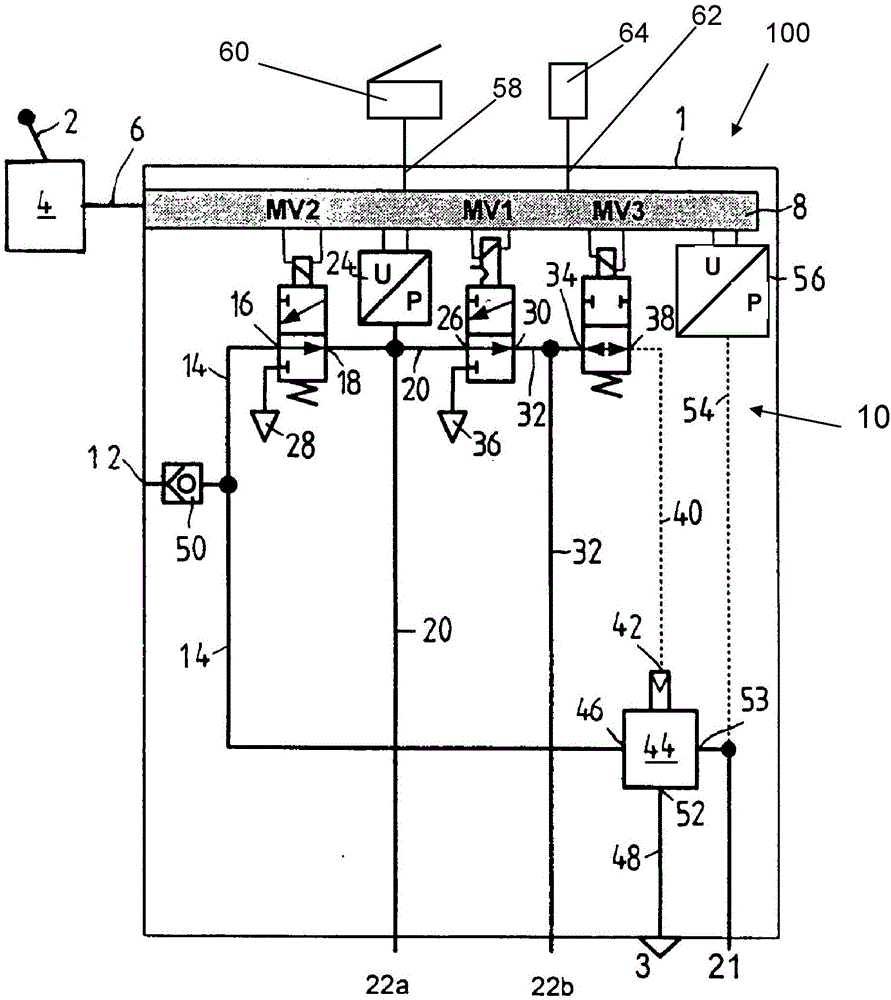
[0047] The electropneumatic parking brake device 100 is figure 1 The preferred embodiment shown in is part of a pressure-medium-actuated, for example electropneumatically actuated, brake system of a tractor-trailer combination and is arranged in the tractor. This relates in particular to an electronically regulated braking system (EBS).

[0048] The electropneumatic parking brake device 100 comprises a parking brake module 1 , symbolically indicated by a square frame, and a parking brake signal transmitter 4 which is manually activated, for example via a brake actuating mechanism. , which is set here, for example, via the actuating lever 2 , the parking brake signal transmitter actuates the electronic control unit 8 of the parking brake module 1 via the electronic signal line 6 via an electrical actuating signal.

[0049] Electronic control unit 8 is preferably integrated into parking brake module 1 . In addition, a solenoid valve device 10 , which can be controlled by the c...


PUM


Abstract

The invention relates to an electropneumatic spring brake device (1) of a motor vehicle, including means for generating electric brake actuation signals that represents at least the "brake application" state and the "brake release" state; an electronic controller (8) which receives the brake actuation signals; an electropneumatic valve device (10) which is controlled by the electronic controller (8) dependent on the actuation signals; and at least one pneumatically actuated spring brake cylinder. The electropneumatic valve device (10) aerates the at least one spring brake cylinder by connecting to a compressed air supply (12) or de-aerates the spring brake cylinder by connecting to a pressure sink (3). A maximally aerated state, which can be brought about by the electronic controller (8), of the electropneumatic valve device (10) is produced in that the electropneumatic valve device (10) releases a maximum flow cross-section between the compressed air supply (12) and the at least one spring brake cylinder. According to the invention, the electronic controller (8) is designed to keep the electropneumatic valve device (10) in the maximally aerated state when switching from the "brake application" state to the "brake release" state while the vehicle is traveling until the pressure in the at least one spring brake cylinder is abruptly increased from a starting pressure value lying below a first gradient to a relatively higher first pressure value which still lies below a brake release pressure that fully releases the spring brake cylinder, and after the first pressure value has been reached, the electropneumatic valve device is switched to a state in which the pressure in the at least one spring brake pressure cylinder is increased from the first pressure value lying below a second gradient that is smaller than the first gradient to a second pressure value that is higher than the first pressure value in order to assume a partial release position or a full release position.

Description

technical field [0001] According to the preamble of claim 1, the invention proceeds from an electropneumatic spring energy storage brake device for a motor vehicle, which comprises means for generating at least The device of the electric brake operating signal in the "release" state, the electronic control device receiving the brake operating signal, the electropneumatic valve device controlled by the control electronic device according to the operating signal, and at least one pneumatically operated spring energy storage brake cylinder, wherein the electro-pneumatic valve device charges at least one spring-loaded brake cylinder by being connected to a compressed air source, and is ventilated by being connected to a decompression port, and wherein there is an electro-pneumatic valve device capable of A state of maximum inflation caused by said electronic control unit in which the electropneumatic valve device opens a maximum flow cross-section between said compressed air sourc...

Claims


Application Information

Patent Timeline
Patent Type & Authority Applications(China)
IPC IPC(8): B60T13/66B60T13/74
CPCB60T13/662B60T13/683B60T13/743B60T7/107B60T11/10B60T13/24B60T13/26B60T13/38B60T13/385B60T13/66B60T13/68B60T13/70B60T13/74B60T15/02B60T15/027B60T17/08B60T17/18B60T8/248B60T8/327
Inventor M·赫格斯S·黑格R·魏兰M·克卢钦斯基
Owner KNORR-BREMSE SYST FUER NUTZFAHRZEUGE GMBH
Why Eureka
Try Eureka