
A plantar pressure detection device and a sports assisting device equipped with the device

A detection device and plantar pressure technology, applied in sports accessories, gymnastics equipment, muscle training equipment, etc., can solve the problems of distortion of measurement results, high cost, inaccurate measurement, etc., and achieve easy installation and fixation, strong bearing capacity, The effect of high reliability

Active Publication Date: 2019-07-26
SHENZHEN CONCHIN TECH CO LTD
View PDF8 Cites 0 Cited by
  • Summary
  • Abstract
  • Description
  • Claims
  • Application Information

AI Technical Summary

Problems solved by technology

[0003] The existing foot measuring device is not optimized enough for the design of the sensor and mechanical structure, and there are problems such as inaccurate measurement, insufficient firmness of the foot measuring device, too complicated structure, high cost, and low reliability.
[0004] Patent CN2006800006514.1 and the 2010 master's thesis of the University of Science and Technology of China "Research on a Flexible Biped Powered Robot Perception System for Gait Detection" both disclose a plantar pressure detection device, which uses a flexible oil pressure tube to sense the foot pressure. The bottom pressure, the problem brought by this device is that the contact pressure area of ​​the oil pressure pipe is difficult to measure accurately, resulting in inaccurate measurement
Patent CN201410036599.4 discloses a plantar pressure detection device, which uses several force-measuring floats to measure the plantar pressure. The problem is that the structure is complex, the cost is high, and when the pressure is applied to the edge of the device, the measurement result will be severely distorted
Patent CN201410491074.X discloses a foot end force detection device, which has a complex structure and high cost, and there is also the situation that when the pressure is applied to the edge of the device, the measurement result will be inaccurate, and the device only bears force at a single point, and the structure is not firm. Long-term use is easy to damage

Method used


Image

  • A plantar pressure detection device and a sports assisting device equipped with the device
  • A plantar pressure detection device and a sports assisting device equipped with the device
  • A plantar pressure detection device and a sports assisting device equipped with the device

Examples


Embodiment 1

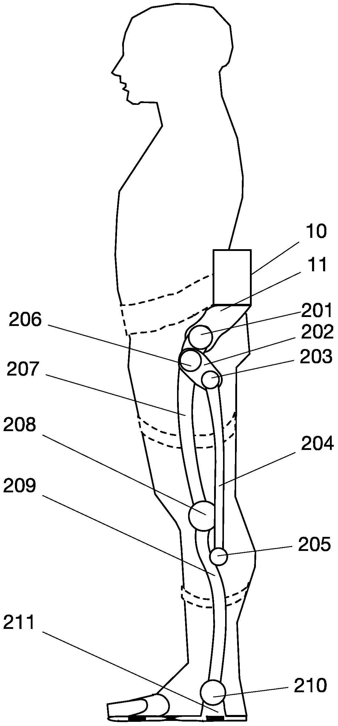
[0048] The plantar pressure detection device of the present invention is applied to a motion assisting device. Such as figure 1 As shown, the motion assisting device includes a power system, a control system and an actuator, and the power system and the control system are installed and fixed in a fixing device 10 at the waist of the human body, and the lower end of the fixing device 10 is provided with an extension section 11 to the hip joint , the lower end of the extension section 11 is installed with the actuator.

[0049] The actuator includes a connecting rod structure that cooperates with the lower limbs of the human body to bear weight. The connecting rod structure includes a thigh connecting section 207 , a lower leg connecting section 209 , a first connecting rod 202 , a second connecting rod 204 and a foot structure 211 . The upper end of the thigh connection section 209 is fixed to the lower end of the waist extension section 11 through the transmission shaft 201, ...

Embodiment 2

[0053] The structure of this embodiment 2 is similar to that of embodiment 1, except that the structure of the plantar pressure detection device is different.

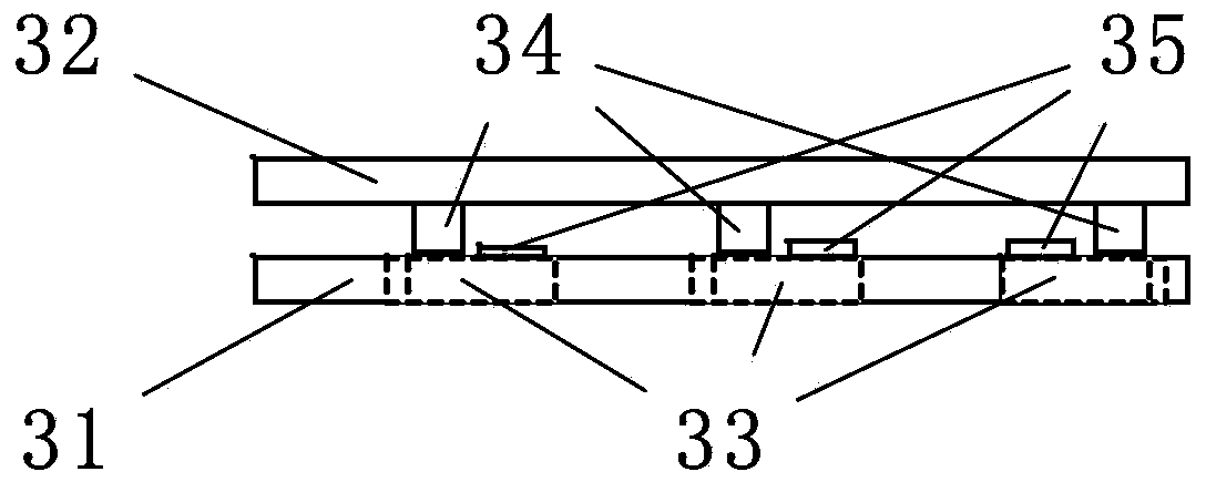
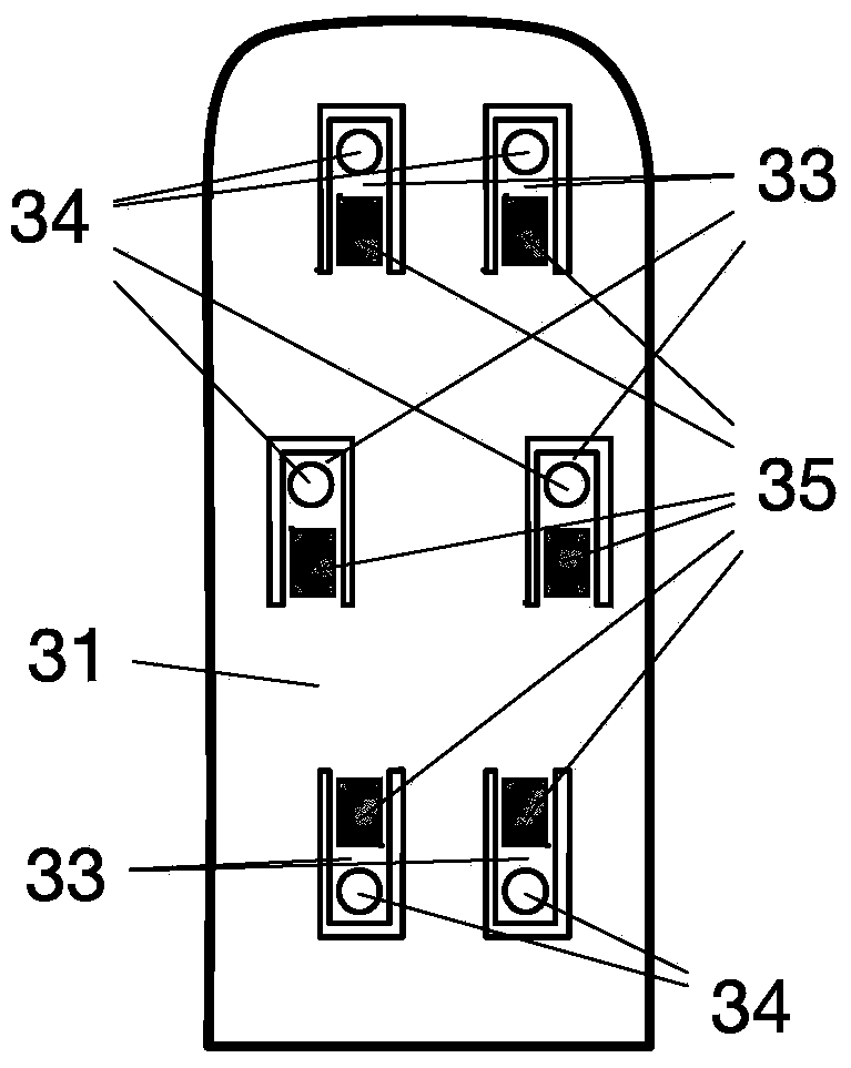
[0054] Such as Figure 4 and Figure 5 As shown, in Embodiment 2, the plantar pressure detection device is provided with three rigid thin plates in parallel, wherein the first rigid thin plate 31 is hollowed out with four first hollow deformation cantilevers 33, and in addition four second hollow deformation cantilever 33a, the second hollow deformation cantilever 33a is respectively equipped with a second sensor 35a for monitoring the deformation of the second hollow deformation cantilever 33a, the second sensor 35a is installed on the lower surface of the second hollow deformation cantilever 33a, the first The second sensor 35a is installed close to the connection between the second hollow deformable cantilever 33a and the first rigid thin plate 31 . A third rigid thin plate 36 is arranged below the first rigid thi...

Embodiment 3

[0057] The structure of this embodiment 3 is similar to that of embodiment 2, except that the structure of the plantar pressure detection device is different.

[0058] Such as Figure 6 , Figure 7 and Figure 8 As shown, the left side of the first rigid thin plate 31 extends outward, and the extension part is bent upwards, and the bent part and the mechanical base 211 are fixed together by a plurality of screws 37. In this way, the device of the present invention is firmly connected with the wearable exoskeleton device fixed together. By adopting the device of this embodiment, the plantar pressure of the human body and the mechanical pressure of the exoskeleton can be measured simultaneously.

[0059] The lower end of the ankle joint shaft 210 is connected to the mechanical base 211 , which is used to bear the mechanical pressure of the exoskeleton. The first rigid thin plate 31 is bent on the left side and fixed together with the mechanical base 211 by a plurality of scre...


PUM


Abstract

A plantar pressure detection device comprises a first rigid thin plate. The first rigid thin plate is provided with a plurality of first hollow-out shape-changing suspension arms; a first sensor is arranged on each first hollow-out shape-changing suspension arm; a second rigid thin plate is mounted over the first rigid thin plate; the first rigid thin plate is connected with the second rigid thin plate via a plurality of first bearing bodies; the lower end of each first bearing body is installed on the first hollow-out shape-changing suspension arm; between the first and second rigid thin plates, all pressure can be directly applied to the hollow-out shape-changing suspension arms via the cylindrical bearing bodies, so measuring loss can be avoided for the measured force; the first hollow-out shape-changing suspension bends and is deformed when pressure is applied; the first sensors can sense the deformation, so an accurate plantar pressure measuring signal can be achieved; the rigid thin plates has strong bearing capacity, thereby being capable of being conveniently and directly connected to other machinery structures and easily installed and fixed; the plantar pressure detection device has simple structure and reliable performance, and is firm; and cost can be greatly reduced.

Description

technical field [0001] The invention relates to a pressure detection device, in particular to a plantar pressure detection device and a motion assisting device equipped with the plantar pressure detection device. Background technique [0002] Wearable exoskeleton devices need to accurately measure the pressure on the wearer's sole and / or the mechanical structure base in real time to sense the wearer's current movement status, so as to implement relevant drive control to realize the motion assist function. Biped robots also need real-time measurement of robot foot pressure to assist in judging the state of the robot. [0003] The existing plantar measuring device is not optimized enough for the design of the sensor and mechanical structure, and there are problems such as inaccurate measurement, insufficient firmness of the plantar measuring device, too complicated structure, high cost, and low reliability. [0004] Patent CN2006800006514.1 and the 2010 master's thesis of the...

Claims


Application Information

Patent Timeline
Patent Type & Authority Patents(China)
IPC IPC(8): A61B5/22
Inventor 余运波邹庆原李凯
Owner SHENZHEN CONCHIN TECH CO LTD
Learn More